volkswagen Workshop Repair Guides

Volkswagen Workshop Service and Repair Manuals

Checking oil in manual gearbox with bevel box > < Removing and installing bevel box (vehicles with 4-cylinder engine)
5-Speed manual gearbox 02C four wheel drive
Removing and installing bevel box
Removing and installing bevel box (Vehicles with 6-cylinder injection engine)

Special tools, testers and auxiliary items

  • ◆ Engine support bracket 10-222A with supports10-222A/1
  • ◆ Socket 6 mm AF V.A.G 1669
  • ◆ Drip tray

Removing

  • ‒ For vehicles with coded radio obtain radio code.
 
V34-2429
  • ‒ With the ignition switched off disconnect the battery earth strap.
  • ‒ → Remove right-hand engine console/sub-frame securing bolt (arrow), first remove cable connector retaining plate -A- if fitted.
 
N34-0667
  • ‒ → Fit support bar 10-222 A together with legs 10-222 A/1 and support engine/gearbox.

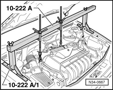
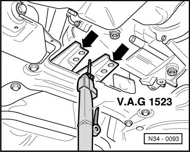
Note:

Before fitting the support hooks of the support bar, remove hose and wire connections from engine in the area of the lifting eyes, so that they are not damaged.

  • ‒ Take weight of engine/gearbox assembly on the spindles.
 
N34-0095
  • ‒ → If fitted, remove air duct -A- for cooling the propshaft bearing (arrow 1) and pull off from front fan connection.
  • ‒ Remove power assisted steering pipe bracket from gearbox.
 
N34-0104
  • ‒ → Remove front console (bolts -A- and -B-).
  • ‒ Remove front engine mounting (bolt -C-).
 
N34-0105
  • ‒ → Remove hexagon bolt -A- from left-hand gearbox assembly mounting -B-.
 
N34-0091
  • ‒ → Remove bevel box carrier from engine and bevel box (arrows) -A-, -B- and -C-.
 
N34-0093
  • ‒ → If fitted cut balance weight mounting (arrows) on assembly carrier off flush using body saw V.A.G 1523. Do not damage assembly carrier.
Warning!
Always wear protective glasses.
  • ‒ If necessary repair paint work damage as follows:
    Remove grease remains with Nitro thinners L 001 600.
    Apply 2 component acrylic paint (ALN 769 041 with hardener ALZ 009 001).
  • ‒ Separate exhaust system behind front exhaust pipe.

=> Repair group 26; Removing and installing parts of exhaust system, four wheel drive.

 
V34-2101
  • ‒ Remove heat shield above catalyst.
  • ‒ Secure catalyst in lowered position.
  • ‒ Mark position of propshaft with flexible coupling to bevel box flange.
  • ‒ → Disconnect propshaft flexible coupling from bevel box flange (arrows).
  • ‒ Push propshaft back onto stop.
 
V39-1817

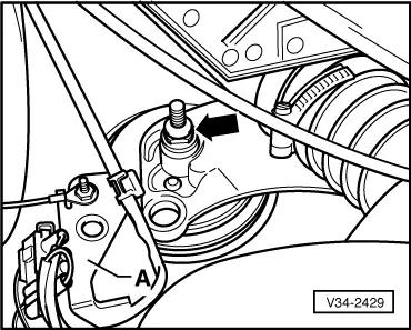
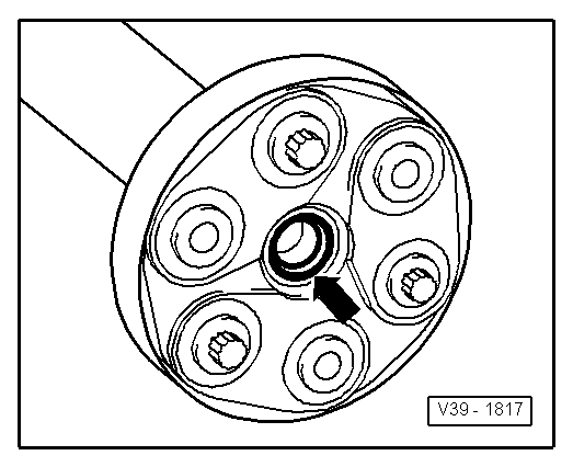
Note:

→ When removing and installing the gearbox do not damage the sealing ring in the propshaft flange.

  • ‒ Disconnect right drive shaft from gearbox.
  • ‒ Tie right drive shaft up as high as possible, when doing this do not damage surface protection.
  • ‒ Place container under the gearbox.
  • ‒ Lever out drive flange sealing cap with a screwdriver.
  • ‒ Remove drive flange counter sunk head bolt with V.A.G 1669 or 6 mm socket insert cone (commercially available) and counter hold against turning with a drift.
  • ‒ Pull drive shaft with drive flange out carefully and note spring behind drive flange.
  • ‒ Remove bevel box/gearbox securing bolts.
  • ‒ Press bevel box off gearbox.
 
V39-1817
  • ‒ Take bevel box out downwards between assembly carrier and sump, to do this push engine/gearbox assembly forwards (2nd mechanic).

Note:

→ When removing and installing the gearbox do not damage the seal in the propshaft flange.

  • ‒ Take out bevel box.

Installing

Installing gearbox is carried out in the reverse sequence. When installing gearbox ensure engine/gearbox mountings are installed stress-free.

 
N34-0025

=> Repair group 10; removing and installing engine.

Notes:

  • ◆ Build bevel box on as follows:
  • ‒ → Always replace sealing ring to seal bevel box/gearbox (arrow A) and sealing rings to seals sleeves for the oil supply system (arrow B and C), lightly coat with oil.
  • ‒ Push bevel box completely onto gearbox, thereby ensuring that the bevel box input shaft teeth are guided centrally onto the differential connecting piece.
  • ‒ If the teeth position and the central guide are correctly set then the bevel box will slide onto the stop against the gearbox.
  • ‒ Do not pull the bevel box onto the gearbox using securing bolts otherwise the bevel box will cant and the securing eyes can break off.
 
N34-0091
  • ◆ When installing the gearbox carrier note following assembly sequence:
  • ‒ → Tighten bolts -A- to 25 Nm.
  • ‒ Tighten bolts -B- and -C- to 40 Nm.
  • ◆ When removing and installing do not damage seals in propshaft flanges.
  • ◆ Renew propshaft if damaged.
  • ◆ Ensure propshaft is horizontal when pushing onto guide pins.
  • ◆ Replacing drive shaft seal.

=> Running gear; Repair group 40; Servicing drive shaft

  • ◆ Installing front exhaust pipe to catalyst

=> Repair group 26; Removing and installing parts of exhaust system.

  • ◆ Checking oil in gearbox with bevel box .
  • ◆ Adjusting gear selector mechanism .

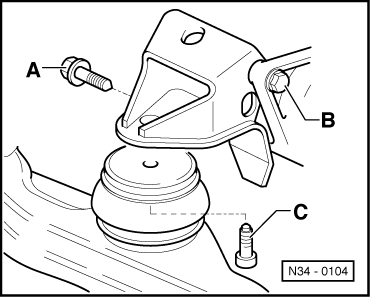
Tightening torques =>from Page 34-51

Checking oil in manual gearbox with bevel box > < Removing and installing bevel box (vehicles with 4-cylinder engine)