
Golf Mk3
| Electrical and electronic components and their locations |
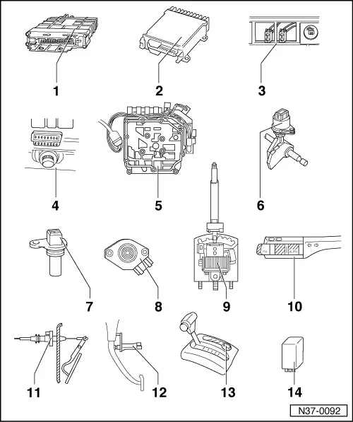
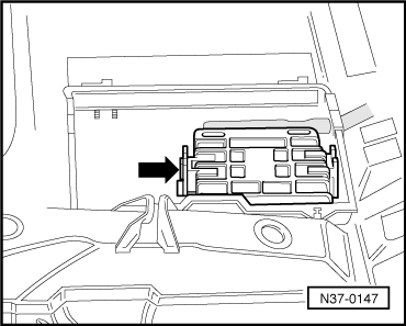
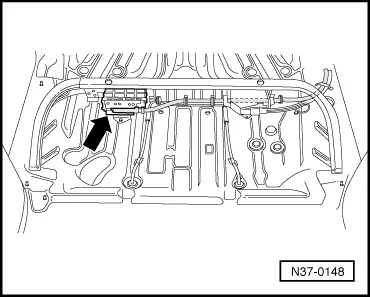
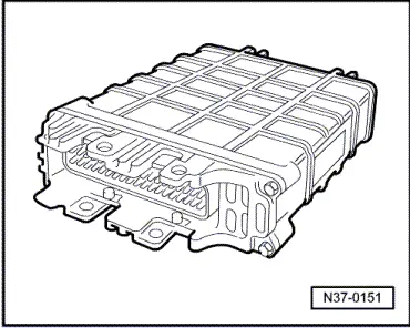
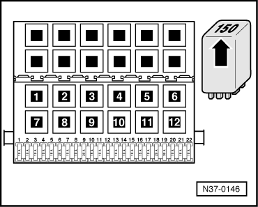
| 1 - | Control unit for automatic gearbox -J217- |
| q | Location and removing and installing through 12.92 → Fig. |
| q | Location and removing and installing from 01.93 → Fig. |
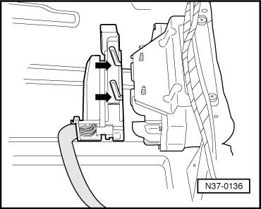
| q | Removing with 68-pin connector → Fig. |
| q | Installing with 68-pin connector → Fig. |
| q | Checked through self-diagnosis → Chapter |
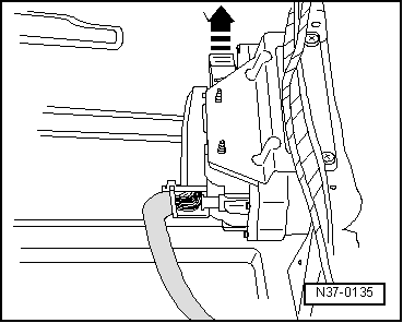
| 2 - | Engine control unit |
| q | Location → Fig. |
| q | Removing and installing → Repair group 24 |
| or |
| q | Removing and installing → Repair group 25 |
 Note
Note| If engine or gearbox control units are renewed, the system must be restored to basic setting → Chapter, Initiating basic setting. |
| 3 - | Diagnostic connection |
| Vehicles through 07.93 |
| q | Location: the diagnosis connection is located beneath the heating and ventilation controls next to the switch for the heated rear window. ⇒ Connecting fault reader -V.A.G 1551- and selecting functions → Chapter |
| 4 - | Diagnostic connection |
| Vehicles from 08.93 |
| q | Location: the diagnosis connection is located behind cover to the right of the ashtray. ⇒ Connecting fault reader -V.A.G 1551- and selecting functions → Chapter |
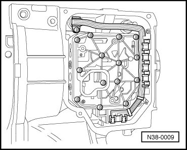
| 5 - | Valve body |
| q | Location → Fig. |
| q | The solenoid valve 1 -N88-, -N89-, solenoid valve 3 -N90-, solenoid valve 4 -N91-, solenoid valve 5 -N92-, solenoid valve 6 -N93-, solenoid valve 7 -N94- and the oil temperature sender -G93- are secured to the valve body. |
| q | If the solenoid valves are wired with a conductor strip, the conductor strip may be removed and installed separately → Chapter. |
| q | Components are checked by self-diagnosis |
| 6 - | Multifunction switch -F125- |
| q | Location and removing and installing → Fig. |
| q | Checked by self-diagnosis |
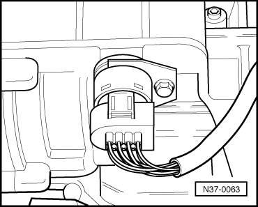
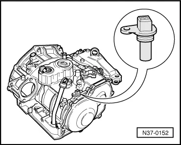
| 7 - | Vehicle speed sender -G68- |
| q | Location and removing and installing → Fig. |
| q | Checked by self-diagnosis |
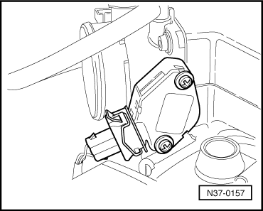
| 8 - | Throttle valve potentiometer -G69- |
| q | Location → Fig. |
| q | Removing and installing → Rep. Gr.24 or → Rep. Gr.25 |
| q | The signal of throttle valve potentiometer is checked by self-diagnosis. |
| q | For vehicles beginning 01.93 with 6-cylinder engines or Simos ignition and injection systems, the signal from the throttle valve potentiometer is transmitted via the engine control unit to the gearbox control unit. The signal can only be checked in measured value block → Chapter. If the throttle valve potentiometer is indicated as a fault, always carry out self-diagnosis of the engine control unit → Repair group 01 for relevant engine code. |
| q | Carry out basic settings after repairs → Chapter. |
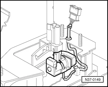
| 9 - | Selector lever lock solenoid -N110- |
| q | Location → Fig. |
| q | Removing and installing → Chapter, Repairing selector mechanism |
| q | Can be checked in measured value block → Chapter and in electrical check → Chapter. |
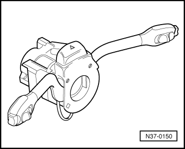
| 10 - | Cruise control system switch -E45- |
| q | Location → Fig. |
| q | Removing and installing → Repair group 94; Repairing steering column switch |
| q | Can be checked in measured value block → Chapter |
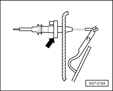
| 11 - | Kickdown switch -F8- |
| q | Location → Fig. |
| q | When removing and installing kickdown switch, remove and install throttle cable and then adjust afterwards |
| q | Adjusting throttle cable → Rep. Gr.20 |
| q | Can be checked in measured value block → Chapter and in electrical check → Chapter. |
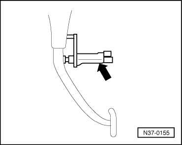
| 12 - | Brake light switch -F- |
| q | Location → Fig. |
| q | Removing and installing → Running gear; Rep. Gr.47 |
| q | Can be checked in measured value block → Chapter and in electrical check → Chapter. |
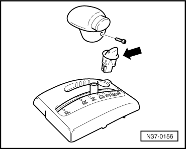
| 13 - | Program switch -E122- |
| q | Location and removing and installing → Fig. |
| q | May be installed as touch switch or rotary switch |
| q | Touch switch and rotary switch may not be interchanged |
| q | Can be checked in measured value block → Chapter and in electrical check → Chapter. |
| q | Not present in vehicles with electronic program switch for gearboxes → Chapter |
| 14 - | Starter inhibitor and reversing light relay -J226- |
| q | Location → Fig. |
|
|
|
|
|
|
|
|
|
|
|
|
|
|
|
|
|
|
|
|
|
|
|
|
|
|
|
|