volkswagen Workshop Repair Guides

Volkswagen Golf Workshop Service and Auto Repair Manuals

Performing self-diagnosis > < Self-diagnosis - Guide
Automatic gearbox self- diagnosis 01M - from 01.95
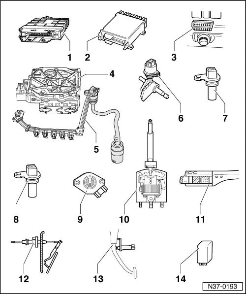
Locations of electrical/electronic components
 
N37-0193
  • Automatic gearbox control unit -J217-
    • ◆ Location => Fig.1
    • ◆ Removing => Fig. 2
    • ◆ Installing => Fig. 3
    • ◆ Checked by self-diagnosis => Carrying out self-diagnosis, Page 01-24
  • Engine control unit
    • ◆ Location => Fig. 4
    • ◆ Removing and installing

=> Repair Group 24 or 25

If engine or gearbox control units are replaced, the system must be brought to basic setting , Initiating basic setting.

 
N37-0193
  • Diagnosis connection
    • ◆ Location => Fig. 5
  • Valve body
    • ◆ Location => Fig. 6
    • ◆ The solenoid valves -N88-, -N89-, -N90-, -N91-, -N92-, -N93- and -N94- are attached to the valve body
    • ◆ Components are checked by self-diagnosis
  • Conductor strip with integrated gearbox oil temperature sender (ATF) -G93-
    • ◆ Location => Fig. 7
    • ◆ Removing and installing =>Fig. 8
    • ◆ -G93- is checked by self-diagnosis
  • Multifunction switch -F125-
    • ◆ Location and removing and installing =>Fig. 9
    • ◆ Checked by self-diagnosis
 
N37-0193
  • Gearbox speed sender -G38-
    • ◆ Location and removing and installing =>Fig. 10
    • ◆ The connector T2 to wiring loom is white
    • ◆ Checked by self-diagnosis

Do not interchange connector T2 for senders -G38- and -G68-

  • Road speed sender -G68-
    • ◆ Location and removing and installing =>Fig. 11
    • ◆ The connector T2 to wiring loom is black
    • ◆ Checked by self-diagnosis

Do not interchange connector T2 for senders -G38- and -G68-

 
N37-0193
  • Throttle valve potentiometer -G69-
    • ◆ Location => Fig. 12
    • ◆ Removing and installing

=> Repair Group 24 or 25

    • ◆ Various types of throttle valve potentiometer according to engine version.
    • ◆ On vehicles with 6-Cyl. engine, TDI engine or Simos injection and ignition system, the throttle valve potentiometer signal is directed via engine control unit to gearbox control unit. The signal can only be checked in measured value block => Page 01-50 . If a fault is indicated in the throttle valve potentiometer, then also carry out a self-diagnosis on engine control unit

=> Repair group 01; for relevant engine code

    • ◆ After repairs initiate basic setting => Page 01-48
    • ◆ The signal of throttle valve potentiometer is checked by self-diagnosis.
 
N37-0193
  • Solenoid for selector lever lock -N110-
    • ◆ Location => Fig. 13
    • ◆ Can be checked electrically => page 01-50
  • Cruise control switch -E45-
    • ◆ Location => Fig. 14
    • ◆ Removing and installing

=> Repair Group 94; Servicing steering column switch

    • ◆ Can be checked via reading measured value block
      => page 01-50
 
N37-0193
  • Kickdown switch -F8-
    • ◆ Location => Fig. 15
    • ◆ When removing and installing kickdown switch, remove and install the throttle cable, then adjust afterwards
    • ◆ Adjusting throttle cable

=> Repair Group 20

    • ◆ Can be checked electrically => page 01-50
  • Brake light switch -F-
    • ◆ Location: => Fig. 16
    • ◆ Removing and installing

=> Repair group 47; Assembly overview: Pedal cluster, brake pedal

    • ◆ Can be checked electrically => page 01-50
  • Relay for starter lock-out and reversing light -J226-
    • ◆ Location => Fig.17
 
N37-0148

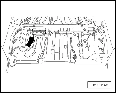
→ Fig.1     Location of automatic gearbox control unit -J217-

The control unit -arrow- is located under the rear seat.

 
N37-0135

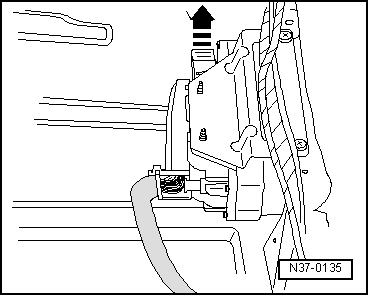
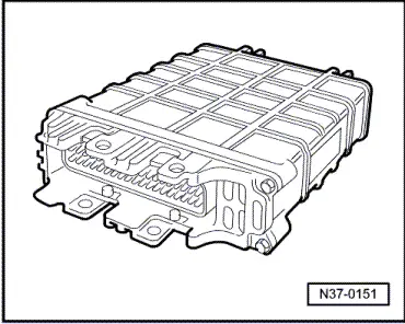
→ Fig.2     Removing automatic gearbox control unit -J217-

  • ‒ Release multi-pin connector, then pull connector off control unit.
  • ‒ Remove control unit.
 
N37-0136

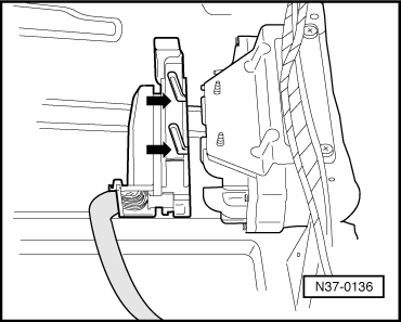
→ Fig.3     Installing automatic gearbox control unit -J217-

  • ‒ Locate multi-pin connector on control unit -J217- pins (arrows) then lock multi-pin connector.
 
N37-0151

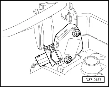
→ Fig.4     Engine control unit

Location: The control unit is located in plenum chamber, right.

Removing and installing control unit

=> Repair group 24 or 25

 
N37-0177

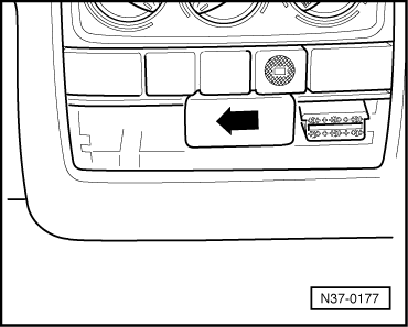
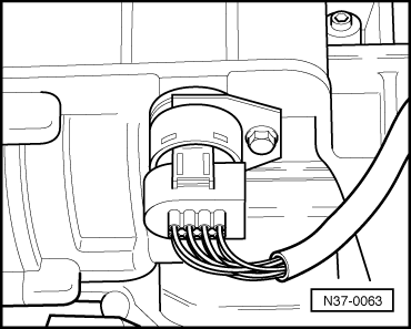
→ Fig.5     Diagnosis connections

Location: The diagnosis connections are located behind the cover next to the ashtray.

  • ‒ → Remove ashtray and slide cover for diagnostic connections to left -arrow-.
 
N38-0026

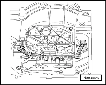
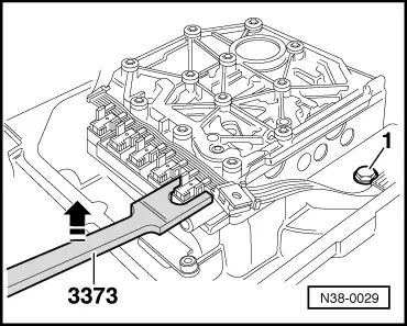
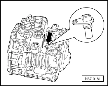
→ Fig.6     Valve body

Location: The valve body is located above oil pan.

The solenoid valves -N88-, -N89-, -N90-, -N91-, -N92-, -N93- and -N94- are attached to the valve body.

Removing and installing valve body

=> Repair group 38; Removing and installing valve chest

in booklet:

  • ◆ Workshop Manual Golf 1992 ä , Vento 1992 ä , Automatic gearbox 01M - from 01.95
 
N38-0026

→ Fig. 7     Conductor strip with integrated gearbox oil temperature sender (ATF) -G93-

Location: The conductor strip is located in the oil pan on the valve body.

The conductor strip can be changed with gearbox installed without removing the valve body.

Do not kink or damage the conductor strip.

 
N38-0029

→ Fig.8     Removing and installing conductor strip

Removing and installing conductor strip

  • ‒ Separate connector at gearbox and remove retaining clamp, drain ATF remove oil pan then remove cable guide.
  • ‒ Lever conductor strip off solenoid valve in direction of arrow with special tool 3373.

If the locating points are damaged the valve body must be exchanged.

Installation is performed in the reverse order.

 
N37-0063

→ Fig.9     Multi-function switch -F125-

Location: The multi-function switch is located on rear of gearbox.

Removing and installing multi-function switch

  • ‒ Pull connector off multi-function switch.
  • ‒ Remove bolt and retainer.
  • ‒ Remove multi-function switch.
  • ‒ Renew seal.

Installation is performed in the reverse order.

  • ‒ Tighten bolt to10 Nm .
 
N37-0181

→ Fig.10     Gearbox speed sender -G38-

Location: The gearbox speed sender -arrow- is located on top of gearbox.

Removing and installing gearbox speed sender

  • ‒ Pull connector off sender.
  • ‒ Remove bolt and pull sender out.
  • ‒ Renew seal.

Installation is performed in the reverse order.

  • ‒ Tighten bolt to 10 Nm.
 
N37-0176

→ Fig.11     Road speed sender -G68-

Location: The road speed sender -arrow- is located on top of gearbox.

Removing and installing road speed sender

  • ‒ Pull black connector off sender.
  • ‒ Remove bolt and pull sender out.
  • ‒ Renew seal.

Installation is performed in the reverse order.

  • ‒ Tighten bolt to 10 Nm.
 
N37-0157

→ Fig.12     Throttle valve potentiometer -G69-

Location: The throttle valve potentiometer is located on the throttle valve housing (engine). Construction can vary, according to engine.

Removing and installing throttle valve potentiometer

Removing and installing is described in relevant injection and ignition assembly group, compare engine code.

=> Repair Group 24 or 25

 
N37-0149

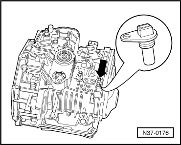
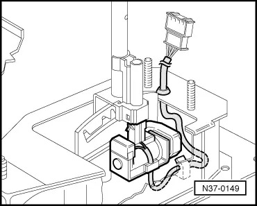
→ Fig.13     Selector lever lock solenoid -N110-

Location: The selector lever lock is located on selector lever.

Removing and installing selector lever lock solenoid

=> Repair group 37; Servicing selector lever mechanism

in booklet:

  • ◆ Workshop Manual Golf 1992 ä , Vento 1992 ä , Automatic gearbox 01M - from 01.95
 
N37-0150

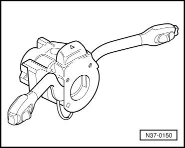
→ Fig.14     Cruise control system switch -E45-

Location: Cruise control switch is located on steering column switch.

Removing and installing cruise control switch

=> Servicing steering column switch; Repair group 94

 
N37-0154

→ Fig.15     Kickdown switch -F8-

Location: Kickdown switch (arrow) is integrated into accelerator cable and is located on bulk head in engine compartment.

Removing and installing kickdown switch

  • ‒ Remove the accelerator cable to remove and install the kickdown switch, then reinstall cable and adjust.

=> Repair group 20; Adjusting accelerator cable

 
N37-0155

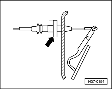
→ Fig.16     Brake light switch -F-

Location: Brake light switch (arrow) is located on pedal cluster.

Removing and installing brake light switch

=> Repair group 47; Assembly overview: Pedal cluster, brake pedal

 
N37-0146

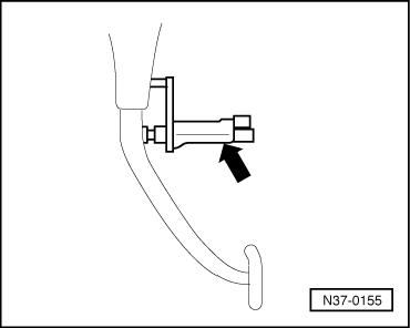
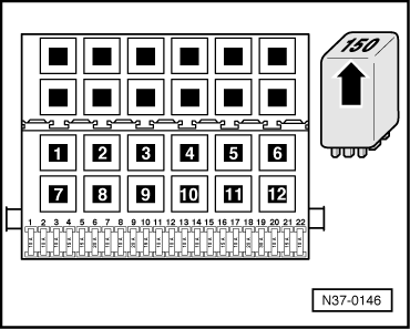
→ Fig.17     Relay for starter inhibitor and reversing light -J226-

Location: Relay located on additional relay carrier under dash panel, left.

Relay can be marked with the number "175" or "150" (arrow).

Performing self-diagnosis > < Self-diagnosis - Guide