volkswagen Workshop Repair Guides

Volkswagen Workshop Service and Repair Manuals

Checking piston projection at TDC > < Crankshaft dimensions
4-Cyl. diesel engine, Mechanics
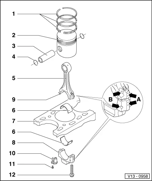
Dismantling and assembling pistons and conrods
 
V13-0958
  • Piston ring
    • ◆ Offset gaps by 120 °
    • ◆ Remove and install with piston ring pliers
    • ◆ "TOP" faces towards piston crown
    • ◆ Checking ring gap=> Fig. 1
    • ◆ Checking ring to groove clearance
      => Fig. 2
 
V13-0958
  • Piston
    • ◆ Engine codes 1Z, AHU, AEY, AFN, AVG, ALE with combustion chamber
    • ◆ Mark installation position and cylinder number
    • ◆ Mark installation position and allocation piston/cylinder for engine codes 1Z, AHU, AEY, AFN, AVG, ALE => Fig. 4
    • ◆ Arrow on piston crown points to pulley end
    • ◆ Install using piston ring clamp
    • ◆ Cracks on piston skirt, renew piston
    • ◆ Checking piston projection at TDC
      =>Page 13-53
 
V13-0958
  • Piston pin
    • ◆ If difficult to remove, heat piston to 60 °C
    • ◆ Remove and install with VW 222a
    • ◆ ø = 26 mm for engine codes 1Z, AHU, AAZ, AEY, AFN, AVG, ALE
      ø = 24 mm for engine code 1Y
  • Circlip
  • Conrod
    • ◆ Only renew as a set
    • ◆ Mark cylinder number -A-
    • ◆ Installation position:
      Marking -B- faces towards pulley end
    • ◆ Length:
      Engine codes
      1Z, AHU, AAZ, AEY, AFN, AVG, ALE
      = 144 mm
      1Y = 150 mm
 
V13-0958
  • Bearing shell
    • ◆ Note version:
      for engine code AFN, AVG upper bearing shell (faces towards piston) of more durable material
      Identification:
      Black line on running surface in area of joint
    • ◆ Note installation position
    • ◆ Do not interchange used bearing shells
    • ◆ Ensure retaining lugs fit tightly in recesses
    • ◆ Axial clearance
      Wear limit: 0.37 mm
    • ◆ Check radial clearance with Plastigage:
      Wear limit: 0.08 mm
      Do not rotate crankshaft when checking radial clearance
    • ◆ Width:
      Engine codes
      1Z, AHU, AAZ, AEY, AFN, AVG,
      ALE = 20 mm
      1Y = 19 mm
 
V13-0958
  • Cylinder block
    • ◆ Checking cylinder bores
      =>Fig. 3
    • ◆ Piston and cylinder dimensions
      =>Page 13-55
  • Conrod bearing cap
    • ◆ Note installation position
  • Fitted pin
    • ◆ The fitted pin must seat securely in the conrod, not in the bearing cap
  • Oil spray jet
    • ◆ For piston cooling
  • 10 Nm
    • ◆ Install with AMV 188 100 02
  • Conrod bolt, 30 Nm + 1/4 turn (90 °) further
    • ◆ Renew
    • ◆ Oil threads and contact surface
    • ◆ To measure radial clearance use old bolts
 
V13-0016

→ Fig. 1     Checking piston ring gap

  • ‒ Push ring squarely from above down to approx. 15 mm from bottom end of cylinder.

Piston ring
Dimensions in mm

New

Wear limit

1st Compression ring
1Z, AHU, AEY,
AFN, AVG, ALE
1Y, AAZ


0.20...0.40
0.20...0.40


1.0
1.2

2nd Compression ring
1Z, AHU, AEY,
AFN, AVG, ALE
1Y, AAZ


0.20...0.40
0.20...0.40


1.0
0.6

Oil scraper ring
1Z, AHU, AEY,
AFN, AVG, ALE
1Y, AAZ


0.25...0.50
0.25...0.50


1.0
1.2

 
V13-0687

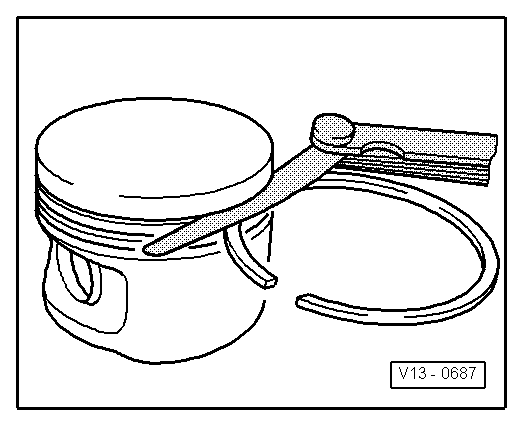
→ Fig. 2     Checking ring to groove clearance

Clean groove before check.

Piston ring
Dimensions in mm

New

Wear limit

1st Compression ring
1Z, AHU, AEY,
AFN, AVG, ALE
1Y, AAZ


0.06...0.09
0.09...0.12


0.25
0.25

2nd compression ring

0.05...0.08

0.25

Oil scraper ring

0.03...0.06

0.15

 
V13-0280

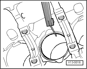
→ Fig. 3     Checking cylinder bores

Special tools, workshop equipment, testers, measuring instruments and auxiliary items required

  • ◆ Internal dial gauge 50...100 mm
  • ‒ Take measurements at 3 positions in both lateral -A- and longitudinal -B- directions, as illustrated. Deviation from nominal dimension
         max. 0.10 mm

Note:

Measuring the cylinder bores must not be done when the cylinder block is mounted on a repair stand with adapter bracket VW 540, as incorrect measurements would then be possible.

 
V13-1204

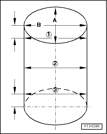
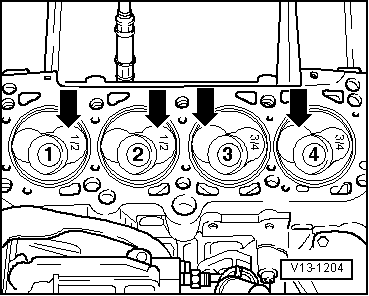
→ Fig.4     Piston installation position and piston/cylinder allocation

Piston in cylinders 1 and 2:

Larger inlet valve chamber towards flywheel -arrows-

Piston in cylinders 3 and 4:

Larger inlet valve chamber towards belt pulley side -arrows-.

Note:

New piston allocation to cylinders is shown by a coloured marking on piston crown.

  • ◆ Piston for cylinder 1 and 2:
    marked 1/2
  • ◆ Piston for cylinder 3 and 4:
    marked 3/4

Checking piston projection at TDC > < Crankshaft dimensions