
Golf Mk3
|
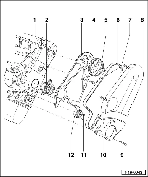
Removing and installing parts of cooling system
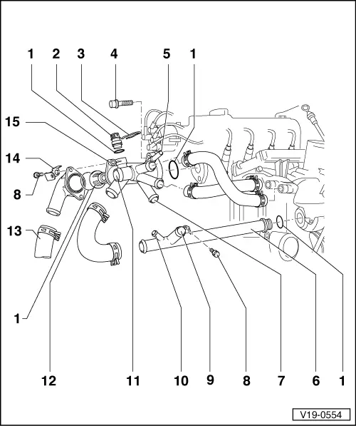
Parts of cooling system - engine side
|
 |
|
|
Thermostat side Engine codes ABD, ABU
|
|
|
|
 |
|
|
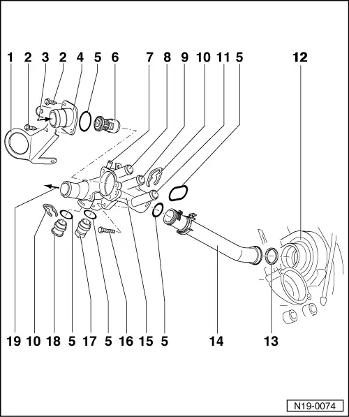
Engine code AEA |
|
|
 |
|
|
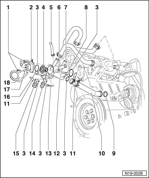
Engine code AEE, AEX, APQ
|
|
|
|
|
|
 |
|
|
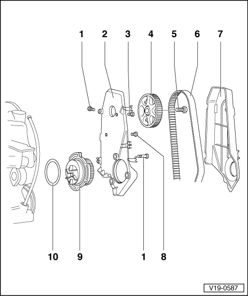
Coolant pump side Engine codes ABD, ABU
|
|
|
|
 |
|
|
Engine code AEE, AEX, APQ
|
|
|
 |
|
|
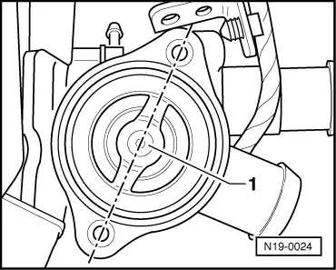
→ Fig.1 Thermostat installation position Engine codes ABD, ABU The thermostat bridge support -1- must align with the threaded holes in the housing. |
 |
|
|
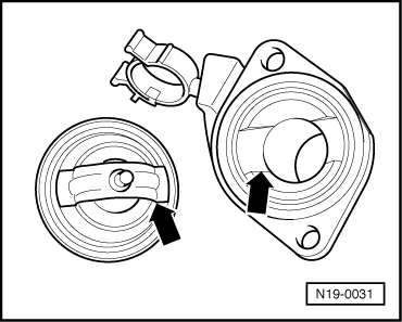
→ Fig.2 Thermostat installation position Engine code AEA The thermostat bridge support must lie in the cut-out of the housing connection piece. |