
Golf Mk3
|
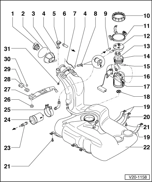
Removing and installing parts of fuel supply system
Removing and installing fuel tank with its attachments
|
 |
|
|
Note: Please ensure after all repairs to the fuel supply unit and the fuel gauge sender, the corrugated hoses/hoses between delivery unit and fuel tank flange do not make contact with the fuel tank, otherwise pump noises will be transmitted. |
|
|
|
|
|
=> Repair group 24; Mixture preparation, injection
|
|
|
=> Current flow diagrams, Electrical fault finding and Fitting locations
|
|
|
|
 |
|
|
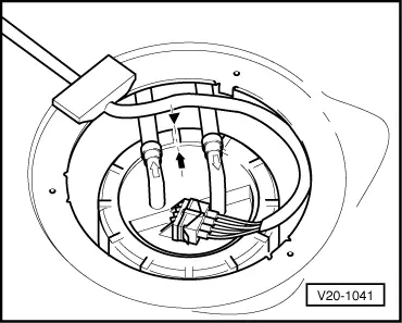
→ Fig. 1 Installation position of fuel delivery unit flange Marking on the flange must align with marking on the fuel tank. |
 |
|
|
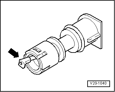
→ Fig. 2 Checking vent valve Lever in rest position: Closed Lever pushed in direction of arrow: Open |