
Golf Mk3
|
Removing and installing parts of fuel supply system
Checking fuel pump
|
 |
|
|
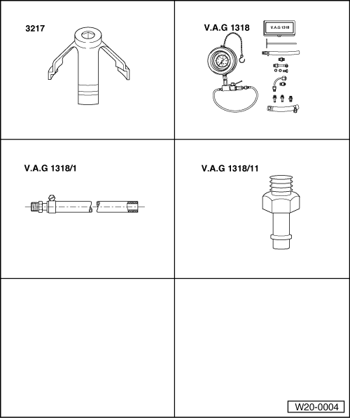
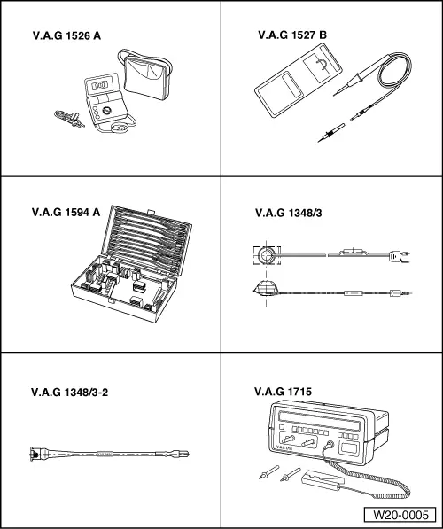
Special tools, workshop equipment, test and measuring appliances and auxiliary items required
|
 |
|
|
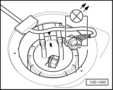
Fuel pump must be heard to run briefly. If the fuel pump does not run:
Notes:
Fuel pump runs:
=> Current flow diagrams, Electrical fault finding and Fitting locations
Fuel pump does not run:
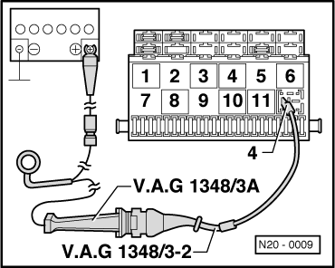
|
 |
|
LED does not light up:
=> Current flow diagrams, Electrical fault finding and Fitting locations binder LED lights up (voltage supply OK.):
If not open circuit can be found:
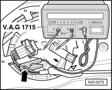
Checking delivery rate The specification for this test is dependent upon fuel pump pressure.
|
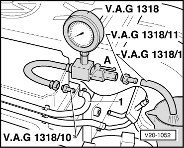 |
|
Note: To prevent fuel spray when loosening connections wrap a cloth around the connection.
Vehicles ▸07.95
|
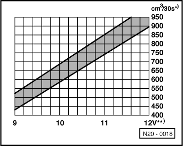 |
|
*) Minimum delivery cm3/30 seconds **) Voltage at fuel pump with engine stopped and pump running (approx. 2 volts less than battery voltage). Vehicles 08.95 ▸
|
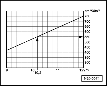 |
|
*) Minimum delivery cm3/30 seconds **) Voltage at fuel pump with engine stopped and pump running (approx. 2 volts less than battery voltage). Example: During the test a voltage of 12.2 volts is measured at the battery. As the voltage at the pump is approx. 2 volts less than the battery voltage then this will equate to a minimum delivery of 550 cm3/30 s. For all vehicles: If the minimum delivery rate is not attained:
|
 |
|
If the minimum delivery rate is now attained:
If the minimum delivery rate is again not attained:
Only when up to now no fault has been detected:
If the delivery rate has been attained but nevertheless you suspect a fuel supply system fault (e.g. intermittent failure of fuel supply system):
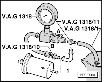
|
|
|
Warning!
Danger of spray when opening the shut-offtap, hold container over the free connection of the pressure gauge.
|