volkswagen Workshop Repair Guides

Volkswagen Workshop Service and Repair Manuals

Checking intake air temperature sender > < Checking clutch pedal switch
Diesel direct injection and glow plug system
Checking components and functions
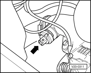
Checking intake manifold temperature sender

(Engine codes AFN, AVG, AHU, ALE, 1Z only)

Special tools, workshop equipment, testers, measuring instruments and auxiliary items required

  • ◆ Fault reader V.A.G 1551 or vehicle system tester V.A.G 1552 with cable V.A.G 1551/3
  • ◆ Test box V.A.G 1598/18
  • ◆ Hand multimeter V.A.G 1526 or multimeter V.A.G 1715
  • ◆ Adapter set V.A.G 1594
  • ◆ Current flow diagram

Test sequence

  • ‒ Connect fault reader V.A.G 1551 (V.A.G 1552). Start engine and select "Address word" 01 of engine control unit. When doing this the engine must be running at idling speed.
    (Connecting fault reader and selecting engine control unit .)
 
→ Indicated on display:
Rapid data transfer     HELP
Select function XX
  • ‒ Press keys 0 and 8 for the function "Read measured value block" and confirm entry with Q key.
 
→ Indicated on display:
Read measured value block     HELP
Input display group number XXX
  • ‒ Press keys 0, 0 and 7 for "Display group number 7" and confirm entry with Q key.
 
→ Indicated on display:
Read measured value block 7     ⇒
15.4 5C          15.9 5C     16.7 5C
  • ‒ If the figure in display zone 3 is not realistic or a substitute temperature of 18.9 °C or 136.8 °C is displayed, check intake air temperature sender and the wiring to sender as follows:
  • ‒ Press the ⇒key.
  • ‒ Press keys 0 and 6 for the "End data transfer" function and confirm input with the Q key.
  • ‒ Switch off ignition.
 
V23-0311
  • ‒ Pull connector off sender => Fitting locations overview, Page 23-8 .
  • ‒ → Carry out resistance measurement between contacts using hand multimeter V.A.G 1526.
 
N24-0157
  • → Specification see diagram

Scale A shows resistance values for temperature range 0...50 °C and scale B the values for temperature range 50...100 °C.

Examples:

  • ◆ 30 °C corresponds to a resistance from 1500...2000 ω
  • ◆ 80 °C corresponds to a resistance from 275...375 ω

If the specification is not obtained:

  • ‒ Replace intake manifold temperature sender (G72).

If the specification is obtained:

 
V96-0749
  • ‒ Connect test box .
  • ‒ → Check wiring between test box and connector for open circuit according to current flow diagram.
         Contact 1+ socket 64
         Contact 2+ socket 33
         Wire resistance: max. 1.5 ω
  • ‒ Additionally check wires for short to one another, to vehicle earth and to battery positive.
         Specification: ∞ω

If no wiring fault is detected:

  • ‒ Renew Diesel direct injection system control unit (J248) => Page 23-118 .

Checking intake air temperature sender > < Checking clutch pedal switch