volkswagen Workshop Repair Guides

Volkswagen Workshop Service and Repair Manuals

Checking needle lift sender > < Checking fuel temperature sender
Diesel direct injection and glow plug system
Checking components and functions
Checking modulating piston movement sender and quantity adjuster

The metering unit is an electromagnetic swivelling positioner which is controlled by the control unit via a directed duty cycle (on-off ratio). The eccentric shaft on the metering unit moves the modulating piston on the high pressure piston and thereby regulates the quantity of fuel injected.

The modulating piston movement sender informs the control unit of the position of quantity adjuster -N146 and therefore stipulates the amount injected.

Special tools, workshop equipment, testers, measuring instruments and auxiliary items required

  • ◆ Fault reader V.A.G 1551 or vehicle system tester V.A.G 1552 with cable V.A.G 1551/3
  • ◆ Test box V.A.G 1598/18
  • ◆ Hand multimeter V.A.G 1526 or multimeter V.A.G 1715
  • ◆ Adapter set V.A.G 1594
  • ◆ Current flow diagram

Test sequence

  • ‒ Connect fault reader V.A.G 1551 (V.A.G 1552). Start engine and select "Address word" 01 of engine control unit. When doing this the engine must be running at idling speed.
    (Connecting fault reader and selecting engine control unit .)
 
→ Indicated on display:
Rapid data transfer     HELP
Select function XX
  • ‒ Press keys 0 and 8 for the function "Read measured value block" and confirm entry with Q key.
 
→ Indicated on display:
Read measured value block     HELP
Input display group number XXX
  • ‒ Press keys 0, 0 and 1 for "Display group number 1" and confirm entry with Q key.
 
→ Indicated on display:
Read measured value block 1     ⇒
840 rpm     6.5 mg/H     1.480 V     87.3 5C
  • ‒ Check coolant temperature in display zone 4.
         Specification: at least 85 °C

Continue with check only when coolant temperature is attained.

     
    → Check voltage supply from modulating piston movement sender in display zone 3.
         Specification:
         Engine codes 1Z, AHU:
         1.250...1.750 V
         Engine code AFN, AVG: 1.450...1.900 V
         Engine code AEY: 1.450...1.800 V
         Engine code ALE: 1.350...2.100 V
    Read measured value block 1     ⇒
    840 rpm     6.5 mg/H     1.480 V     87.3 5C
  • ‒ If specification is not obtained, check modulating piston movement sender and quantity adjuster as described in following:
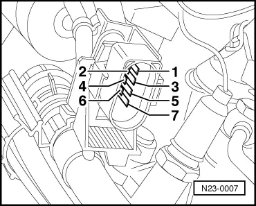
  • Checking modulating piston movement sender (G149).

    • ‒ Press the ⇒key.
    • ‒ Press keys 0 and 6 for the "End data transfer" function and confirm input with the Q key.
    • ‒ Switch off ignition.
     
    N23-0007
    • ‒ Disconnect connector for sender
      =>Fitting locations overview, Page 23-4 .
    • ‒ → Carry out resistance measurement between contacts 1 + 2 and 2 + 3 using hand multimeter V.A.G 1526.
           Specification: 5 ... 7 ω

    If the specification is not obtained:

    • ‒ Replace injection pump => Page 23-25 .

    If the specification is obtained:

    • ‒ Connect test box .
     
    N23-0008
    • ‒ → Check wiring between test box and connector for open circuit according to current flow diagram.
           Contact 1+ socket 29
           Contact 2+ socket 7
           Contact 3+ socket 52
           Wire resistance: max. 1.5 ω
    • ‒ Additionally check wires for short to one another, to vehicle earth and to battery positive.
           Specification: ∞ω

    If no wiring fault is detected:

    • ‒ Renew Diesel direct injection system control unit (J248) => Page 23-118 .

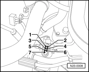
    Checking quantity adjuster (N146)

    • ‒ Press the ⇒key.
    • ‒ Press keys 0 and 6 for the "End data transfer" function and confirm input with the Q key.
    • ‒ Switch off ignition.
    • ‒ Separate connector for quantity adjuster =>Fitting locations overview, Page 23-4 .
     
    N23-0007
    • ‒ → Carry out resistance measurement between contacts 5 + 6 using hand multimeter V.A.G 1526.
           Specification: 0.5 ... 2.5 ω

    If the specification is not obtained:

    • ‒ Replace injection pump => Page 23-25 .

    If the specification is obtained:

    • ‒ Connect test box .

    Engine codes AFN, AVG, AHU, 1Z:

     
    N23-0008
    • ‒ → Check wiring between test box and connector for open circuit using current flow diagram.
           Contact 5+ sockets 23, 45 and 68
           Contact 6+ sockets 4, 5, 30 and 49
           Wire resistance: max. 1.5 ω
    • ‒ Additionally check wires for short to one another, to vehicle earth and to battery positive.
           Specification: ∞ω

    Engine codes AEY, ALE:

    • ‒ Check wiring between test box and connector for open circuit using current flow diagram.
           Contact 5+ sockets 23, 45 and 68
           Contact 6+ sockets 4, 5 and 49
           Wire resistance: max. 1.5 ω
    • ‒ Additionally check wires for short to one another, to vehicle earth and to battery positive.
           Specification: ∞ω

    If no wiring fault is detected:

    • ‒ Renew Diesel direct injection system control unit (J248) => Page 23-118 .

    Checking needle lift sender > < Checking fuel temperature sender