volkswagen Workshop Repair Guides

Volkswagen Workshop Service and Repair Manuals

Checking coolant temperature sender > < Checking sender for throttle valve positioner
Mono Motronic injection and ignition system
Mono-Motronic injection and ignition system
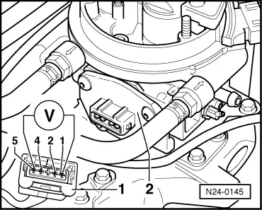
Checking throttle valve potentiometer

Special tools, testers and auxiliary items

  • ◆ Fault reader V.A.G 1551 or vehicle system tester V.A.G 1552 with
         ▸ 07.93: Cable V.A.G 1551/1
         08.93 ▸: Cable V.A.G 1551/3
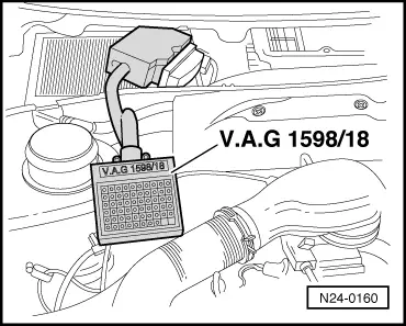
  • ◆ Test box V.A.G 1598/18
  • ◆ Hand multimeter V.A.G 1526 or multimeter V.A.G 1715
  • ◆ Adapter set V.A.G 1594
  • ◆ Current flow diagram

Test sequence

  • ‒ Remove air cleaner or air intake elbow.
  • ‒ Connect fault reader V.A.G 1551 (V.A.G 1552) and select engine electronics control unit (address word 01); carry out selection with ignition switched on.
 
→ Indicated on display:
Rapid data transfer     HELP
Select function XX
  • ‒ Input 08 for "Read measured value block" function and confirm with Q.
 
→ Indicated on display:
Read measured value block     HELP
Input display group number XX
  • ‒ Input 00 for "Display group number" and confirm with Q.
 
→ Indicated on display:
(1...10 = Display zones)
Read measured value block     0     ⇒
     1     2     3     4     5     6     7     8     9     10
  • ‒ Slowly open throttle valve fully and observe the numerical figures in display zones 2 and 3.
  • Display zone 2:
         The numerical figure must increase uniformly until throttle                valve is 1/4 open and then remain constant
  • Display zone 3:
         The numerical figure must increase uniformly over the entire
         range
  • ‒ Press ⇒ key.
  • ‒ Input 06 for "End output" and confirm with Q.

If one or both figures remain constant:

 
N24-0145
  • ‒ Switch off ignition
  • ‒ → Pull 5 pin connector -1- off throttle valve potentiometer -2-.
  • ‒ Connect multimeter with aux. cables from V.A.G 1594 to measure voltage at contacts 1+5 of the connector.
  • ‒ Switch on ignition and measure voltage
         Specification: approx. 5 V
 
N24-0160
  • ‒ → Connect test box V.A.G 1598/18 to control unit wiring loom.
  • ‒ Check wiring between test box and 5 pin connector for open circuit according to current flow diagram.
         Contact 1+socket 17
         Contact 2+socket 41
         Contact 4+socket 18
         Contact 5+socket 14
         Wire resistance: Max. 1.5 ω
  • ‒ Additionally check wires for short to one another.
         Specification: ∞ω

If no wiring fault is detected and voltage was present between contacts 1+5:

  • ‒ Replace lower part of injection unit.

If no wiring fault is detected and no voltage was present between contacts 1+5:

  • ‒ Renew Mono Motronic control unit (J257)
    , item 2 .

Checking coolant temperature sender > < Checking sender for throttle valve positioner