|
Measured value blocks
Evaluating measured value blocks
|
Display group 1 -Basic functions-
|
|
Read measured value block 1
|
⇒
|
[ltrif ] Indicated on display
|
|
|
|
xxxx rpm
|
xx.x °C
|
xx.x %
|
xx.x° BTDC
|
|
|
|
|
1
|
2
|
3
|
4
|
[ltrif ] Display zones
|
Specification
|
Evaluation
|
|
|
|
|
|
Ignition angle
|
0...13.5 ° BTDC
|
---
|
|
|
|
|
Lambda regulator
|
-20...20 %
|
|
|
|
|
Coolant temperature
|
80...105 °C
|
=> Page 01-68
|
|
|
Engine speed (idling speed)
|
650...750 rpm
|
=> Page 01-67
|
Notes on display zone 2:
The engine control unit will use the intake air temperature as a replacement value for an engine start (start temperature - replacement value) as soon as there is a fault stored in the fault memory, which affects the coolant temperature sender (G62). The temperature then rises according to a model stored in the control unit. When the engine has reached normal working temperature a fixed replacement value will be displayed after a certain period. This fixed value is also dependent upon the intake air temperature.
Note on display zone 3:
-
◆ The display must fluctuate around 0. If constant 0 is displayed, the Lambda regulation has switched from regulation to control, because there is a fault in the Lambda regulation. Interrogate fault memory => Page 01-13
.
|
Display group 1 -Basic functions- for control unit number: 021906258A ... CK
|
|
Read measured value block 1
|
⇒
|
[ltrif ] Indicated on display
|
|
|
|
xxxx rpm
|
xx.x °C
|
x.xx
|
xx.x° BTDC
|
|
|
|
|
1
|
2
|
3
|
4
|
[ltrif ] Display zones
|
Specification
|
Evaluation
|
|
|
|
|
|
Ignition angle
|
0...13.5 ° BTDC
|
---
|
|
|
|
|
Lambda factor
|
0.97... 1.03
|
=> Page 01-69
|
|
|
|
Coolant temperature
|
80...105 °C
|
=> Page 01-68
|
|
|
Engine speed (idling speed)
|
650...750 rpm
|
=> Page 01-67
|
Notes on display zone 2:
The engine control unit will use the intake air temperature as a replacement value for an engine start (start temperature - replacement value) as soon as there is a fault stored in the fault memory, which affects the coolant temperature sender (G62). The temperature then rises according to a model stored in the control unit. When the engine has reached normal working temperature a fixed replacement value will be displayed after a certain period. This fixed value is also dependent upon the intake air temperature.
Note on display zone 3:
-
◆ If the figures are higher or lower than the specification when the engine is warm this leaning or enriching of the mixture (caused by unmetered air or a defective injection system) can lead to a fault being entered. Interrogate fault memory => Page 01-13
.
Evaluating display group 1, display zone 1 - Engine speed (idling speed)
|
|
|---|
|
V.A.G 1551 display
|
Possible fault cause
|
Fault elimination
|
|
Less than 650 rpm
|
- Throttle valve control part sticking or defective
|
- Check throttle valve control part
=> Page 24-38
|
|
|
- Large amount of unmetered air (cannot be compensated for by the idling stabilisation)
|
- Check intake air system for leaks
=> Page 24-75
|
|
More than 750 rpm
|
- Idling switch not closed/defective
|
- Interrogate fault memory, => Page 01-13
|
|
|
- Large amount of unmetered air (cannot be compensated for by the idling stabilisation)
|
- Check intake air system for leaks
=> Page 24-75
|
|
|
- Throttle valve control part sticking/defective
|
- Check throttle valve control part
=> Page 24-38
|
|
|
- Supply voltage too low, engine tries to reduce charge difference through increased idling speed
|
- Check alternator
=> Page 01-72
|
|
|
- Air conditioner operating too long at idling speed
|
- Switch off air conditioner
|
Evaluating display group 1, display zone 2 - Coolant temperature
|
Appears on display
|
Possible fault cause
|
Fault elimination
|
|
Less than 80 °C
|
- Engine too cold
|
- If necessary carry out test drive
|
|
|
- Coolant temperature sender or wiring to engine control unit
|
- Check coolant temperature sender
|
|
More than 105 °C
|
- Radiator soiled
|
- Clean radiator
|
|
|
- Radiator fan not functioning
|
- Check function
|
|
|
- Thermostat defective (does not open)
|
- Check thermostat
|
|
|
- Coolant temperature sender or wiring to engine control unit
|
- Check coolant temperature sender
|
Evaluating display group 1, display zone 3 - Lambda regulator
|
Appears on display
|
Possible fault cause
|
Fault elimination
|
|
Outside tolerance range
|
- Minus range: Mixture too rich, Lambda control weakens mixture
- Positive range: Mixture too lean, Lambda control enrichens mixture
|
- Wait 30 seconds until the display has stabilised
|
|
|
- Unmetered air
|
- Check intake system for leaks
=> Page 24-75
|
|
|
- Injector defective
|
- Check injection rate => Page 24-83
|
|
Display group 2 -Basic functions-
|
|
Read measured value block 2
|
⇒
|
[ltrif ] Indicated on display
|
|
|
|
xxxx rpm
|
x.xx ms
|
xx.xx V
|
xxxxxxxx
|
|
|
|
|
1
|
2
|
3
|
4
|
[ltrif ] Display zones
|
Specification
|
Evaluation
|
|
|
|
|
|
Exhaust gas recirculation
|
EGR active
EGR not active
|
---
|
|
|
|
|
Control unit voltage supply
|
12.000...14.500 V
|
=> Page 01-72
|
|
|
|
Injection period
|
1.0...3.5 ms
|
=> Page 01-71
|
|
|
Engine speed (idling speed)
|
650...750 rpm
|
=> Page 01-67
|
Notes on display zone 4:
-
◆ "EGR not active" will be displayed on vehicles with a throttle valve control part but not fitted with exhaust gas recirculation.
-
◆ A constant 182 °C or 217.0 °C will be displayed for control unit number 021906258A ... CK when there is no exhaust gas recirculation fitted.
Evaluating display group 2, display zone 2 - Injection period
|
Appears on display
|
Possible fault cause
|
Fault elimination
|
|
Less than 1.00 ms
|
- Large amount of fuel from the activated charcoal filter system
|
- Check activated charcoal filter solenoid valve
|
|
|
- Incorrect injectors with greater throughput installed
|
- Check injection rate => Page 24-83
|
|
|
- Fuel pressure too high
|
- Check fuel pressure regulator
=> Page 24-73
|
|
More than 3.50 ms
|
- Increased engine load due to electric consumers, air conditioner, gear selected or P.A.S. steering on full lock
|
- Eliminate increased load (air conditioner, power assisted steering etc.)
|
Evaluating display group 2, display zone 3 - Control unit voltage supply
|
Appears on display
|
Possible fault cause
|
Fault elimination
|
|
Less than 12.000 V
|
- Generator defective, battery heavily discharged
|
- Check voltage, charge battery
|
|
|
- Battery heavily loaded shortly after starting due to high charging current and current consumers
|
- Increase revs slightly for a few minutes and switch off current consumers
|
|
|
- Transfer resistance in the current supply or the engine control unit earth connection
|
- Check engine control unit voltage supply => Page 24-112
|
|
|
- Current draw when ignition is off
|
- Eliminate current draw
|
|
More than 14.500 V
|
- Voltage regulator in alternator defective
|
- Check voltage, replace regulator if necessary
|
|
|
- Excess voltage due to jump starting or quick charging unit
|
- Interrogate fault memory => Page 01-13
|
|
Display group 3 -Basic functions-
|
|
Read measured value block 3
|
⇒
|
[ltrif ] Indicated on display
|
|
|
|
xxxx rpm
|
x.xx ms
|
x <°
|
xxx.x °C
|
|
|
|
|
1
|
2
|
3
|
4
|
[ltrif ] Display zones
|
Specification
|
Evaluation
|
|
|
|
|
|
Intake air temperature
|
-45...108.5 °C
|
|
|
|
|
|
Throttle valve angle
|
1...5 <°
|
=> Page 01-74
|
|
|
|
Injection period
|
1.0...3.5 ms
|
=> Page 01-71
|
|
|
Engine speed (idling speed)
|
650...750 rpm
|
=> Page 01-67
|
Note on display zone 3:
When the throttle valve angle is shown as 0 at idling speed, the engine control unit recognises overrun cut-off. Match throttle valve control part to engine control unit => Page 24-120
.
Note on display zone 4:
Exact information on specifications is not possible as the display is largely dependent on the ambient temperature.
Evaluating display group 3, display zone 3 - Throttle valve angle
|
Appears on display
|
Possible fault cause
|
Fault elimination
|
|
More than 5 <°
|
- Engine control unit not matched to throttle valve control part
|
- Perform matching to throttle valve control part => Page 01-13
|
|
|
- Throttle valve potentiometer in throttle valve control part defective
|
- Check throttle valve control part
=> Page 24-38
|
|
|
- Accelerator cable adjustment
|
- Adjust accelerator cable
|
|
|
- Throttle valve sticking
|
- Eliminate cause
|
Note:
If the accelerator pedal is floored the value will be 75...95 <°.
|
Display group 3 -Basic functions- for control unit number: 021906258A ... CK
|
|
Read measured value block 3
|
⇒
|
[ltrif ] Indicated on display
|
|
|
|
xxxx rpm
|
x.xx %
|
xx <°
|
xxx.x °C
|
|
|
|
|
1
|
2
|
3
|
4
|
[ltrif ] Display zones
|
Specification
|
Evaluation
|
|
|
|
|
|
Intake air temperature
|
-45...108.5 °C
|
|
|
|
|
|
Throttle valve angle
|
9...19 <°
|
---
|
|
|
|
Engine load
|
1.0...4.0 %
|
---
|
|
|
Engine speed (idling speed)
|
650...750 rpm
|
=> Page 01-67
|
Note on display zone 3:
If the throttle valve angle is outside of the specification at idling speed, check the adjustment of the accelerator cable and then the operating modes => display group 4 display zone 4. Also check the throttle valve potentiometer => Page 24-54
.
Note on display zone 4:
Exact information on specifications is not possible as the display is largely dependent on the ambient temperature.
Evaluating display group 3, display zone 4 - Intake air temperature
|
Appears on display
|
Possible fault cause
|
Fault elimination
|
|
Constant 46.5 °C
or 141.0 °C
|
- Fault on intake manifold temperature sender -G72 recognised
|
- Interrogate fault memory => Page 01-13
|
|
|
- Intake manifold temperature sender -G72
|
- Check intake manifold temperature sender -G72
|
|
Display group 4 -Basic functions-
|
|
Read measured value block 4
|
⇒
|
[ltrif ] Indicated on display
|
|
|
|
xxx.x %
|
xxx.x %
|
xxx.x %
|
xxx.xx
|
|
|
|
|
1
|
2
|
3
|
4
|
[ltrif ] Display zones
|
Specification
|
Evaluation
|
|
|
|
|
|
Tank venting operating mode
|
---
|
---
|
|
|
|
|
Lambda learnt value at idling (additive)
|
-10.0...10.0 %
|
=> Page 01-69
|
|
|
|
Lambda learnt value at part load (multiplicative)
|
-10.0...10.0 %
|
=> Page 01-69
|
|
|
Lambda regulator
|
-20...20 %
|
---
|
Notes on display zone 1:
-
◆ The display must fluctuate around 0. If constant 0 is displayed, the Lambda regulation has switched from regulation to control, because there is a fault in the Lambda regulation. Interrogate fault memory => Page 01-13
.
Noes on display zones 2 and 3:
Low values indicate that the engine is running too rich and therefore the Lambda regulation is leaning the mixture.
-
◆ High values indicate that the engine is running too lean and therefore the Lambda regulation enriches the mixture.
-
◆ If there is no voltage supply to the control unit all the values learnt will be cancelled.
-
◆ add = additive - The effects of the fault (e.g. unmetered air) will reduce as the engine speed increases. The injection period will be modified by a fixed amount for additive learnt values. This amount is not dependent upon the basic injection period.
-
◆ mul = multiplicative - The effects of the fault (e.g. faulty injector) will increase as the engine speed increases. A multiplicative learnt value is a proportional change to the injection period. This change is dependent on the basic injection period.
|
Display group 4 -Basic functions- for control unit number: 021906258A ... CK
|
|
Read measured value block 4
|
⇒
|
[ltrif ] Indicated on display
|
|
|
|
xxxx rpm
|
xxx %
|
xxx km/h
|
xxxxx
|
|
|
|
|
1
|
2
|
3
|
4
|
[ltrif ] Display zones
|
Specification
|
Evaluation
|
|
|
|
|
|
Operating mode (idling)
|
00010
|
---
|
|
|
|
|
Road speed
|
0 km/h
|
---
|
|
|
|
Engine load
|
1.0...4.0 %
|
=> Page 01-69
|
|
|
Engine speed (idling speed)
|
650...750 rpm
|
=> Page 01-67
|
Note on display zone 3:
Checking speed signal => Page 24-127
Note on display zone 4:
Depending upon the operating mode the following is valid: 00001 for overrun cut-off, 00010 for idling, 00100 for part throttle, 01000 for full throttle and 10000 for acceleration enrichment.
|
Display group 5 -Basic functions-
|
|
Read measured value block 5
|
⇒
|
[ltrif ] Indicated on display
|
|
|
|
xxxx rpm
|
xxx %
|
xxx km/h
|
xxxxxx
|
|
|
|
|
1
|
2
|
3
|
4
|
[ltrif ] Display zones
|
Specification
|
Evaluation
|
|
|
|
|
|
Operating mode (idling, part throttle, full throttle, enrichment, overrun)
|
Idling
|
---
|
|
|
|
|
Road speed
|
0 km/h
|
---
|
|
|
|
Engine load
|
10...30 %
|
---
|
|
|
Engine speed (idling speed)
|
650...750 rpm
|
=> Page 01-67
|
Note on display zone 3:
Checking speed signal => Page 24-127
|
Display group 5 -Basic functions- for control unit number: 021906258A ... CK
|
|
Read measured value block 5
|
⇒
|
[ltrif ] Indicated on display
|
|
|
|
xxxx rpm
|
xxx
|
xxx %
|
xx-xx
|
|
|
|
|
1
|
2
|
3
|
4
|
[ltrif ] Display zones
|
Specification
|
Evaluation
|
|
|
|
|
|
Air conditioner/automatic gearbox operating mode
|
xx-xx
|
---
|
|
|
|
|
Idling stabilization
|
Approx. 56%
|
---
|
|
|
|
Adaption requirement of the idling positioner
|
Approx. 0.97
|
---
|
|
|
Engine speed (idling speed)
|
650...750 rpm
|
=> Page 01-67
|
Notes on display zones 2 and 3:
Values in these display zones are not for the service department.
Note on display zone 4:
Depending upon the operating condition the following are valid: 01-xx for air conditioner readiness, 11-xx for air conditioner switched on, xx-10 for gearbox intervention on automatic gearbox, xx-01 for gear selected switch (for manual gearbox always 1)
|
Display group 6 -Basic functions-
|
|
Read measured value block 6
|
⇒
|
[ltrif ] Indicated on display
|
|
|
|
xxxx rpm
|
xx.xx g/s
|
xx.x %
|
xxxxxxxx
|
|
|
|
|
1
|
2
|
3
|
4
|
[ltrif ] Display zones
|
Specification
|
Evaluation
|
|
|
|
|
|
A/C compressor signal on
A/C readiness signal
|
11_ _ _ _ _ 1
01_ _ _ _ _ 0
|
---
|
|
|
|
|
Throttle valve positioner duty cycle learnt value
|
65...80 %
|
|
|
|
|
Idling air mass learnt value
|
-1.70...1.70 g/s
|
---
|
|
|
Engine speed (idling speed)
|
650...750 rpm
|
=> Page 01-67
|
Notes on display zone 2:
-
◆ Displayed is how far the idling stabilisation has "learnt" and moved away from the predetermined design average. If the engine is new the value will be in the positive range due to the high engine friction, and when run-in, in the negative range.
-
◆ The value displayed is not measured by the air mass meter, but calculated from the throttle valve potentiometer information.
|
Display group 7
|
|
Read measured value block 7
|
⇒
|
[ltrif ] Indicated on display
|
|
|
|
xxxx rpm
|
xxxx rpm
|
xx.x %
|
x.x g/s
|
|
|
|
|
1
|
2
|
3
|
4
|
[ltrif ] Display zones
|
Specification
|
Evaluation
|
|
|
|
|
|
Lambda probe voltage
|
0.000...1.100 V
|
=> Page 01-83
|
|
|
|
|
Engine speed (idling speed specification)
|
700 rpm
|
---
|
|
|
|
Engine speed (idling speed specification)
|
700 rpm
|
---
|
|
|
Engine speed (idling speed)
|
650...750 rpm
|
=> Page 01-67
|
Notes on display zone 4:
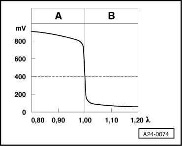
-
◆ The voltage signal "lean mixture (high level of residual oxygen)" is approx. 0.0...0.3 V.
-
◆ The voltage signal "rich mixture (low level of residual oxygen)" is approx. 0.7...1.1 V.
-
◆ When changing from "rich" to "lean" and back again (font=symbol charset=fontspecific code=108 TeX='\lambda ' descr='[lambda]' = 1.0), the voltage will jump from between 0.7 and 1.1 V to between 0.0 and 0.3 V (and back again).
-
◆ Due to the steep voltage jumps the Lambda control cannot keep the ideal mixture composition font=symbol charset=fontspecific code=108 TeX='\lambda ' descr='[lambda]' = 1.0 constant. The control fluctuates constantly between conditions "slightly too lean" and "slightly too rich".
-
◆ The displayed value must temporarily drop below 0.3 V and exceed 0.6 V. Displayed values below 0.45 V signifies lean, above 0.45 V rich.
-
◆ When the displayed value is a constant 0.455 V, this indicates that there is an open circuit in wiring to font=symbol charset=fontspecific code=108 TeX='\lambda ' descr='[lambda]' probe.
|