volkswagen Workshop Repair Guides

Volkswagen Workshop Service and Repair Manuals

Dismantling and assembling intake manifold, engine codes ADY, AGG, AKR > < Fitting locations overview
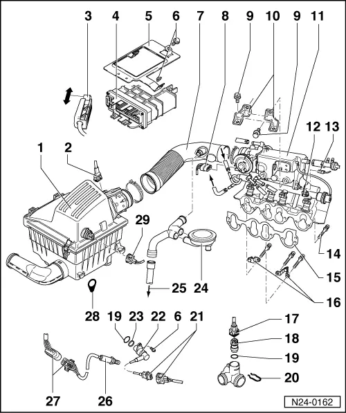
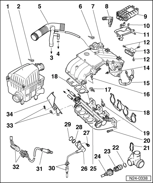
Simos injection and ignition system
Servicing injection part

Servicing ignition part

=> Repair group 28

Notes:

  • ◆ Fuel hoses in engine compartment must only be secured with spring type clips. The use of clamp or screw type clips is not permissible.
  • ◆ The control unit for the fuel injection and ignition system is equipped with a fault memory. Before carrying out repairs, adjustment work and fault finding the fault memory must be interrogated and the vacuum connections checked (outside air).
  • ◆ Components marked with * are checked via the self diagnosis.
    , interrogating fault memory
  • ◆ Components marked with ** are checked via the final control control diagnosis => Page 01-39 .
  • ◆ For trouble-free operation of the electrical components, a voltage of at least 11.5 V is necessary.
  • ◆ Do not use sealants containing silicone. Particles of silicone drawn into the engine, will not be burnt in the engine and damage the Lambda probe.
  • ◆ If the engine starts, runs for a short period and then stops, after fault finding, repairs or component tests, then the fault may lie with the immobilizer which is blocking the engine control unit. The fault memory must be interrogated and if necessary the control unit matched => Page 24-93 .
  • ◆ During some checks it can happen that the control unit will recognise and store a fault. Therefore after completing all checks and repairs the fault memory must be interrogated and if necessary erased.
    => Page 01-9 , interrogating fault memory

Safety precautions

Rules for cleanliness => Page 24-34

Technical data => Page 24-35

Checking engine operation => Page 24-51

 
N24-0162

Engine codes ADY, AGG, AKR

  • Air cleaner
    • ◆ Dismantling and assembling => Page 24-29
  • Connector
    • ◆ 3 pin
    • ◆ For air mass meter (G70)
  • Connector
    • ◆ Only disconnect or connect with ignition switched off
    • ◆ Release to disconnect
 
N24-0162
  • Simos control unit (J361)*
    • ◆ Location: in plenum chamber, right
    • ◆ For injection system, throttle valve control part, Lambda regulation, knock control, activated charcoal filter solenoid valve 1, speed governing via injectors or fuel pump relay, ignition and self diagnosis
    • ◆ Voltage supply via voltage supply relay (J363) and terminal 15
    • ◆ Checking voltage supply => Page 24-90
    • ◆ Checking signal from starter
      => Page 24-97
    • If the control unit is replaced then the following work must be carried out:
    • ◆ Check control unit coding => Page 01-7 , Coding Simos control unit
    • ◆ Perform basic setting => Page 24-39
    • ◆ Match control unit to electronic immobilizer => Page 24-93
 
N24-0162
  • Securing plate
    • ◆ For Simos control unit (J361)
  • 10 Nm
  • Intake hose
  • Connector
    • ◆ 8 pin
    • ◆ For throttle valve control part (J338)
  • 20 Nm
  • Support
    • ◆ Between intake manifold and cylinder head cover
  • Intake manifold
    • ◆ Dismantling and assembling => Page 24-22
  • Connector
    • ◆ 2 pin
    • ◆ For injector
 
N24-0162
  • Connector
    • ◆ For radiator fan run-on sender
  • 25 Nm
  • Gasket
    • ◆ Renew
  • 30 Nm
    • ◆ From warm air collector plate on exhaust manifold
  • Connector
    • ◆ 4 pin
    • ◆ Wiring chamber 1 and wiring chamber 3 for G62
  • Coolant temperature sender (G62)*
    • ◆ Black, with temperature gauge sender (G2)
    • ◆ For Simos control unit
    • ◆ Checking => Page 24-72
    • ◆ If necessary before removing, release pressure from cooling system
 
N24-0162
  • O ring
    • ◆ Renew if damaged
  • Retaining clip
    • ◆ Check seated securely
  • 3 pin connector
    • ◆ For engine speed sender
    • ◆ Black
  • Engine speed sender (G28)*
  • Spacer ring
  • Crankcase breather pressure regulating valve
  • To crankcase
 
N24-0162
  • Lambda probe (G39)*, 50 Nm
    • ◆ Fitting location: catalyst
    • ◆ Grease only the threads with "G5"; "G5" must not get into the slots on the probe body
    • ◆ Checking Lambda probe and Lambda control
      => Page 24-41
    • ◆ Probe heating voltage supply via fuel pump relay (J17)
    • ◆ Checking Lambda probe heating => Page 24-48
  • 4 pin connector
    • ◆ For Lambda probe and Lambda probe heating
    • ◆ Secured to rear engine mounting on right, in direction of travel
  • Retaining ring
  • Connector
    • ◆ 2 pin
    • ◆ For intake air temperature sender (G42)
 
N24-0338

Engine codes AFT, AKS

  • Air cleaner
    • ◆ Dismantling and assembling => Page 24-29
  • Connector
    • ◆ 3 pin
    • ◆ For air mass meter (G70)
  • To crankcase
  • To cylinder head cover
  • Intake hose
  • Connector
    • ◆ 8 pin
    • ◆ For throttle valve control part (J338)
  • Intake manifold
    • ◆ Dismantling and assembling upper part => Page 24-25
    • ◆ Dismantling and assembling lower part => Page 24-28
 
N24-0338
  • Connector
    • ◆ Only disconnect or connect with ignition switched off
    • ◆ Release to disconnect
  • Simos control unit (J361)*
    • ◆ Location: in plenum chamber, right
    • ◆ For injection system, throttle valve control part, Lambda regulation, knock control, activated charcoal filter solenoid valve 1, speed governing via injectors or fuel pump relay, ignition and self diagnosis
    • ◆ Voltage supply via voltage supply relay (J363) and terminal 15
    • ◆ Checking voltage supply => Page 24-90
    • ◆ Checking signal from starter
      => Page 24-97
 
N24-0338
    • If the control unit is replaced then the following work must be carried out:
    • ◆ Check control unit coding => Page 01-7 , Coding Simos control unit
    • ◆ Perform basic setting => Page 24-39
    • ◆ Match control unit to electronic immobilizer => Page 24-93
  • 10 Nm
  • Securing plate
    • ◆ For Simos control unit (J361)
  • 20 Nm
  • Support
    • ◆ Between intake manifold and cylinder head cover
  • Connector
    • ◆ 2 pin
    • ◆ For intake manifold change-over valve (N156)
 
N24-0338
  • To brake servo
  • 20 Nm
  • Connector
    • ◆ 2 pin
    • ◆ For intake air temperature sender (G42)
  • Gasket
    • ◆ Renew
  • Connector
    • ◆ 2 pin
    • ◆ For injector
  • 25 Nm
  • Retaining clip
    • ◆ Check seated securely
  • O ring
    • ◆ Renew if damaged
 
N24-0338
  • Coolant temperature sender (G62)*
    • ◆ Black, with temperature gauge sender (G2)
    • ◆ For Simos control unit
    • ◆ Checking => Page 24-72
    • ◆ If necessary before removing, release pressure from cooling system
  • Connector
    • ◆ 4 pin
    • ◆ Wiring chamber 1 and wiring chamber 3 for G62
  • Intake manifold - lower part
  • Engine speed sender (G28)*
  • 10 Nm
  • Spacer ring
 
N24-0338
  • O ring
    • ◆ Renew if damaged
  • 3 pin connector
    • ◆ For engine speed sender
    • ◆ Black
  • Lambda probe (G39)*, 50 Nm
    • ◆ Fitting location: front pipe
    • ◆ Grease only the threads with "G5"; "G5" must not get into the slots on the probe body
    • ◆ Checking Lambda probe and Lambda control
      => Page 24-41
    • ◆ Probe heating voltage supply via fuel pump relay (J17)
    • ◆ Checking Lambda probe heating => Page 24-48
 
N24-0338
  • 4 pin connector
    • ◆ For Lambda probe and Lambda probe heating
    • ◆ Secured to rear engine mounting on right, in direction of travel
  • M6 = 10 Nm
    M8 = 20 Nm
  • Deflector

Dismantling and assembling intake manifold, engine codes ADY, AGG, AKR > < Fitting locations overview