volkswagen Workshop Repair Guides

Volkswagen Workshop Service and Repair Manuals

Changes to track on Golf/Vento from 08.93 - Model year 1994 > < Dismantling and assembling shock absorber, Golf Variant
Running gear
Servicing rear axle (vehicles with front wheel drive)
 
V42-0866

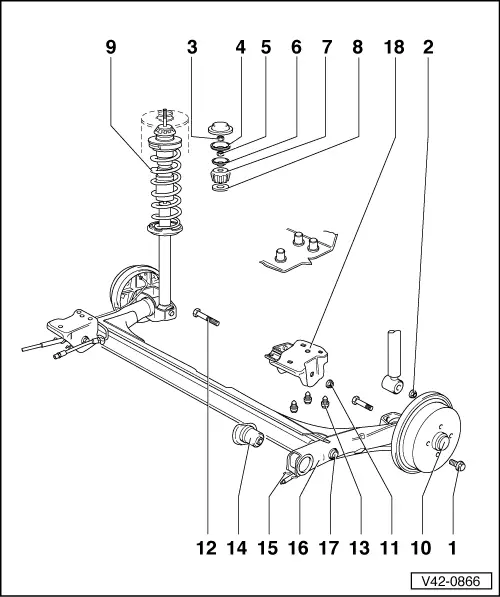
The rear axle and wheel bearings are identical on base and plus running gear.

Note:

Welding and straightening of the axle beam is not permissible.

  • 110 Nm
  • 70 Nm
    • ◆ When tightening the nut the axle beam must be in the horizontal position (unladened vehicle state)
  • 25 Nm
  • Dished washer
  • 15 Nm
  • Cover (large)
 
V42-0866
  • Upper mounting ring (rubber)
  • Cover (small)
  • Suspension strut
    • ◆ Removing and installing=>Fig.1
    • ◆ Dismantling and assembling
  • Wheel bearing
    • ◆ Servicing
      Vehicles with drum brakes
    • ◆ Vehicles with disc brakes
  • 80 Nm
    • ◆ Use only self-locking nuts with captive washers
    • ◆ When tightening nut, the axle beam must be in the horizontal position (unladened vehicle state)
 
V42-0866
  • Bolt
    • ◆ Fit from centre of vehicle
  • Shouldered bolt, 70 Nm
    • ◆ If threads are damaged, rework captive nut in side member
  • Bonded rubber mounting
    • ◆ Pressing out => Fig.2
    • ◆ Pressing in => Fig.3
  • Handbrake cable bracket
  • Axle beam
    • ◆ Stub axle contact surfaces and threaded holes are to be free of paint and dirt
    • ◆ When installing preload bonded rubber mountings, otherwise service life is shortened
      =>Fig.5
    • ◆ Allocation
    • Modification:
 
V42-0866
  • Anti-roll bar
    • ◆ Allocation
  • Mounting bracket with retainer for brake pressure regulator
    • ◆ Installation position => Fig.4 and5
    • ◆ Check and if necessary adjust rear axle total track after installation
    • ◆ If possible do not loosen when removing the rear axle
 
V42-0443

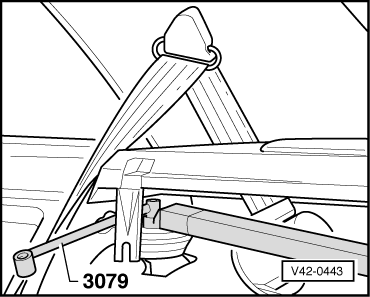
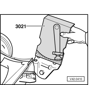
→ Fig.1    Removing and installing suspension strut

 
V42-0868

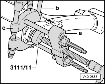
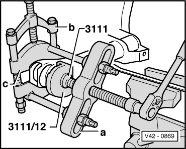
→ Fig.2    Pressing out bonded rubber mounting

Note:

Before pressing out remove corrosion from protruding part of mounting.

a - Bridge

b - Kukko 17 - 2

c - Kukko 15 - 2

 
V42-0869

→ Fig.3    Pressing in bonded rubber mounting

a - Bridge

b - Kukko 17 - 2

c - Kukko 15 - 2

Depth: the cylindrical parts of mounting must protrude 8 mm ± 1.

 
V42-0410

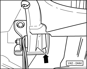
→ Fig.4    Bolting mounting bracket to axle beam (installed position)

Angle of inclination to axle beam 12° ±2°.

 
V42-0444

→ Fig.5    Installing rear axle beam

Note:

The rear axle mountings must be preloaded when installed.

  • ‒ Fit all bolts.
  • ‒ Align the right side of mounting bracket so that the securing bolts are in the centre of the elongated holes.
  • ‒ Using two levers, on the left side, press the mounting bracket against the bonded rubber mounting until only a small gap exists on the inside (arrow).
  • ‒ In this position tighten securing bolts to specified torque.

Changes to track on Golf/Vento from 08.93 - Model year 1994 > < Dismantling and assembling shock absorber, Golf Variant