volkswagen Workshop Repair Guides

Volkswagen Workshop Service and Repair Manuals

Executing self diagnosis > < Fault finding with fault reader V.A.G 1551 on ABS, ITT Mark 04 and ABS/EDL ITT Mark 04 (flow chart)
Running gear self-diagnosis for ABS
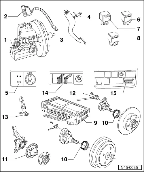
Electrical/electronic components and fitting locations
 
N45-0035
  • ABS hydraulic unit (N55)

The hydraulic unit consists of the components:

    • ◆ Hydraulic pump (V64) with hydraulic pump sender (G101)

=> is checked by the self-diagnosis

    • ◆ Valve block (contains the in/outlet valves, for ABS/EDL additionally the valves for the differential lock and the pressure control switch, which has been deleted from 07.93).
    • ◆ The hydraulic pump (V64) and valve block must not be separated from one another

=> Running gear; Repair group 45

 
N45-0035
    • ◆ When changing the hydraulic unit always seal the old part with the plugs from the repair set Part No.
      1H0 698 311
    • ◆ Hydraulic unit multi-pin connectors
  • EDL series resistance (N159)

=> is checked by the self-diagnosis

    • ◆ Location: On the hydraulic unit (N55)
  • Brake pedal position sender (G100)

=> is checked by the self-diagnosis

  • Brake light switch (F)

=> is checked by the self-diagnosis

    • ◆ The brake light switch is open in the rest position;
    • ◆ Adjusting => Page 01-87
 
N45-0035
  • ABS warning lamp (K47)
    • ◆ Location: In the dash panel
    • ◆ Function:
    • ‒ The ABS control lamp (K47) lights for a few seconds after switching on the ignition
    • ‒ If a fault is recognised (e.g. speed sensor open circuit) it remains on
  • ABS relay (J102)
    • ◆ Location: Above the relay plate
  • ABS hydraulic pump relay (J185)
    • ◆ Location: Above the relay plate
  • EDL relay (J310)

=> is checked by the self-diagnosis

    • ◆ Location: Above the relay plate
 
N45-0035
  • ABS control unit (J104)

=> is checked by the self-diagnosis

    • ◆ Location up to 01.93:
      in footwell, front left below floor mat in front of passenger seat
    • ◆ Location from 01.93:
      under the rear seat, right
    • ◆ Checking the multi-pin connector to control unit
    • ◆ Do not disconnect connector before successful interrogation of fault memory, switch ignition off first.
  • Impulse wheel for rear right and left speed sensors
    • ◆ Installation instructions => Item 13
  • Impulse wheel for front right and left speed sensors
    • ◆ Installation instructions => Item 13
 
N45-0035
  • Rear right/left speed sensor (G44/G46)

=> is checked by the self-diagnosis

    • ◆ Installation instructions => Item 13
  • Front right/left speed sensor (G45/G47)

=> is checked by the self-diagnosis

    • ◆ Before inserting the sensor clean the inner surface of the sensor mounting and coat with lubricating paste
      G 000 650
    • ◆ When connecting the speed sensor wire ensure it is not twisted in the wheel housing
    • ◆ Securing bolt tightening torque;
      10 Nm
 
N45-0035
  • Diagnosis connection
    • Vehicles from 08.93
    • ◆ Location: The diagnosis connection is located behind the cover on the right next to the ashtray
  • Diagnosis connection
    • Vehicles to 07.93
    • ◆ Location: Below the heating/ventilation controls, next to the heated rear window switch

Executing self diagnosis > < Fault finding with fault reader V.A.G 1551 on ABS, ITT Mark 04 and ABS/EDL ITT Mark 04 (flow chart)