
Golf Mk4
|
 Note
Note
|
|
|
|
|
|
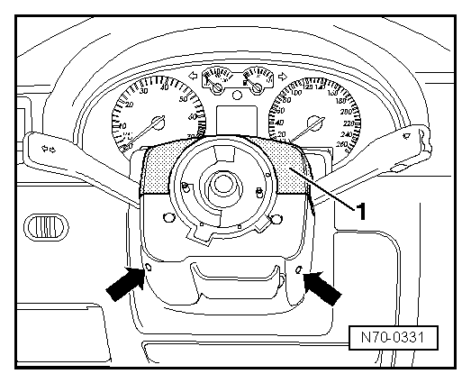
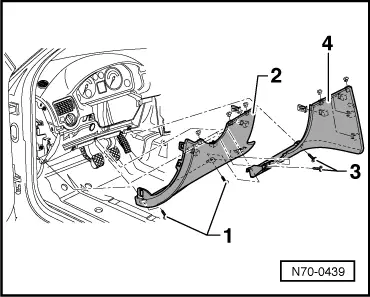
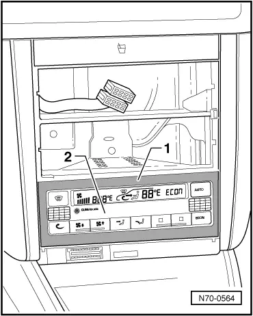
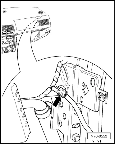
| – | Unclip locking part on left and right with a flat screwdriver. |

|
|
|
|
Note
|
|
|
|
Note
|
|
|
|
|
|
|
|
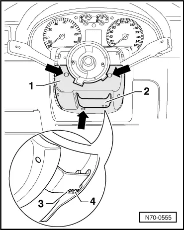
| – | Unclip seat heating switches -2- and -3- using a flat screwdriver -1-. |
| – | Detach connectors. |
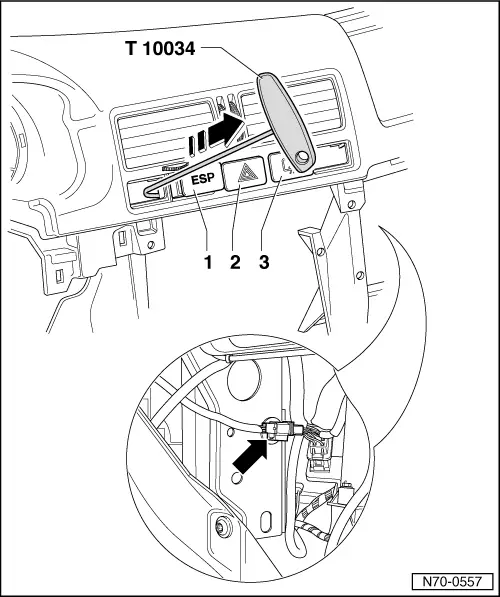
Note| Due to the higher strength spring in locking mechanism for ESP, hazard warning light and heated rear window switches, they cannot be removed with a screwdriver. |
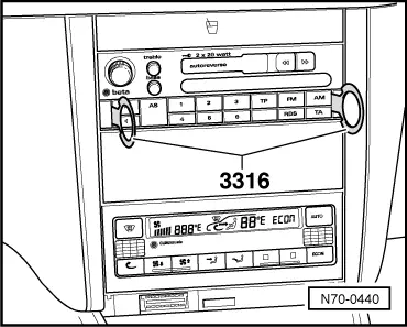
| – | Insert point from assembly tool -T10034- behind ESP switch. |

| – | Using assembly tool -T10034- unclip ESP switch -1-, hazard warning light switch -2- and heated rear window switch -3- out of centre vent in direction of arrow. |
| – | Detach connectors. |
| Bora/Bora estate only: |
| – | Separate connector for vent light -arrow-. |
| All vehicles: |
| – | Press in light switch -1-, turn to right and pull out. |
| – | Detach connector. |
| – | Remove screw -2- and pull vent out of dash panel. |
| – | Detach headlight range control connector -3-. |
| Bora/Bora estate only: |
| – | Separate connector for vent light -4-. |

|
|
Note
|
|
 WARNING
|
|
|
|
|
|
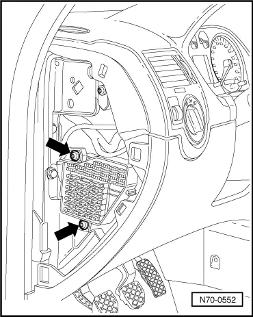
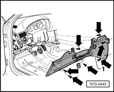
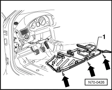
| – | Remove seven bolts -arrow- (torque setting 3 Nm). |
| – | Pull dash panel -1- off cross-member -2-. |
