| –
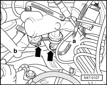
| Pull connector -arrows- off brake pressure senders -a- and -b-. |
| Continuation for all vehicles |
| –
| Unscrew brake lines on brake master cylinder and seal brake lines with plugs from repair kit Part No. 1H0 698 311 A. |
| –
| Unscrew brake master cylinder nuts. |
| –
| Remove heat shield, if part of original equipment. |
| –
| Carefully take brake master cylinder out of brake servo unit. |
| –
| Install in reverse order. |
| Observe the following points when installing: |
| –
| When fitting together the brake master cylinder and brake servo unit, ensure that the push rod is correctly located in the brake master cylinder. |
| –
| Initiate basic (default) settings to bleed brake system. |
| Connecting -VAS 5051- and selecting functions → Chapter. |
| –
| Basic settings of brake pressure sender 1 -G201- and brake pressure sender 2 -G214- must be performed in addition on vehicles with ABS/EDL/TCS/ESP (only Mark 20 IE). |
|
|
|