
Golf Mk4
| Parts of cooling system - engine side |
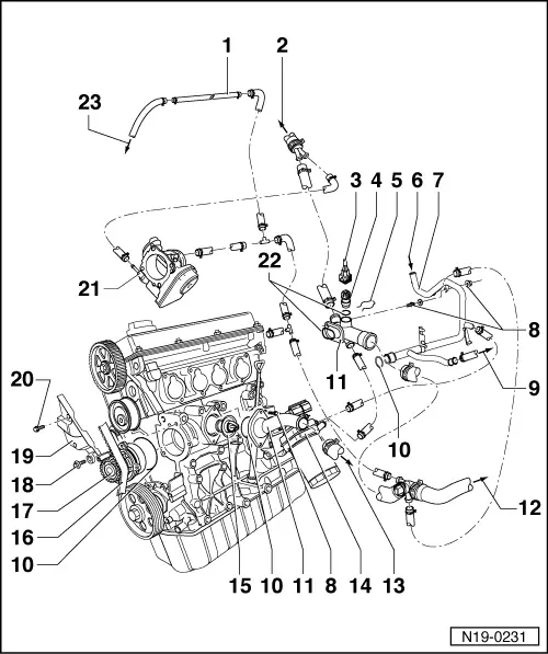
| 1 - | Upper coolant pipe |
| q | Clipped onto bulkhead |
| q | Coolant hose schematic diagram → Chapter. |
| 2 - | To heat exchanger |
| q | Coolant hose schematic diagram → Chapter. |
| 3 - | Connector |
| q | 4-pin. |
| q | Wire of chamber 1 or C and wire of chamber 3 or D for coolant temperature sender -G62- |
| q | Contacts for coolant temperature sender -G62-, gold-plated |
| 4 - | Sender for coolant temperature sender -G62- |
| q | For engine control unit. |
| q | With sender for coolant temperature gauge sender -G2- |
| q | Contacts for coolant temperature sender -G62-, gold-plated |
| q | If necessary, release pressure in cooling system before removing. |
| q | Checking: → Rep. Gr.01 |
| 5 - | Securing clip |
| q | Check for secure seating. |
| 6 - | From heat exchanger |
| q | Coolant hose schematic diagram → Chapter. |
| 7 - | Coolant pipe |
| q | Coolant hose schematic diagram → Chapter. |
| 8 - | 10 Nm |
| 9 - | To bottom of expansion tank |
| q | Coolant hose schematic diagram → Chapter. |
| 10 - | O-ring |
| q | Renew |
| 11 - | Connection |
| q | Coolant hose schematic diagram → Chapter. |
| 12 - | To top of radiator |
| q | Coolant hose schematic diagram → Chapter. |
| 13 - | To bottom of radiator |
| q | Coolant hose schematic diagram → Chapter. |
| 14 - | Oil cooler |
| q | Ensure clearance to adjacent components. |
| q | See note → Chapter. |
| q | Coolant hose schematic diagram → Chapter. |
| 15 - | Thermostat |
| q | Checking: heat thermostat in water. |
| q | Opening begins at approx. 86 °C. |
| q | Opening lift min. 7 mm. |
| q | Removing and installing → Chapter. |
| 16 - | Toothed belt |
| q | Mark D.O.R. before removing. |
| q | Check for wear. |
| q | Do not kink. |
| q | Removing, installing and tensioning → Chapter. |
| 17 - | Coolant pump |
| q | Check for ease of movement. |
| q | If damaged or leaking, renew complete. |
| q | Removing and installing → Chapter. |
| 18 - | 15 Nm |
| 19 - | Rear toothed belt guard |
| 20 - | 20 Nm |
| 21 - | Throttle valve control module |
| q | Heated by coolant. |
| q | Coolant hose schematic diagram → Chapter. |
| 22 - | O-ring |
| q | Renew if damaged. |
| 23 - | To top of expansion tank |
| q | Coolant hose schematic diagram → Chapter. |