volkswagen Workshop Repair Guides

Volkswagen Workshop Service and Repair Manuals

Colour markings > < Removing and installing drive plate
4cyl. Injection Engine, (2.0 ltr. Engine) (Mexico)
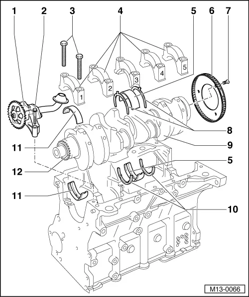
Removing and installing crankshaft
 
M13-0066

Notes:

  • ◆ Before removing the crankshaft, ensure that a suitable place has been prepared, to ensure that the sender wheel (item 6) is free and does not get damaged.
  • ◆ When stripping and assembling the engine it should be secured to the engine frame with engine and gearbox bracket VW 540 and supplementary set VW 540/1B.
  • Oil pump
    • ◆ With pressure relief valve of 12 bar
    • ◆ Before installing, check that both dowel sleeves for centralising oil pump/cylinder block are fitted
    • ◆ Removing and installing
 
M13-0066
  • 15 Nm
  • 65 Nm + 90 ° (1/4 turn) further
    • ◆ Renew
    • ◆ Threaded along complete length (screw)
    • ◆ Tighten to 65 Nm when measuring crankshaft radial clearance
  • Bearing cap
    • ◆ Bearing cap 1: Poly V-belt pulley end
    • ◆ Bearing cap 3 with recesses for thrust washers
    • ◆ Bearing shell retaining lugs (cylinder block/bearing cap) must be on the same side
  • Bearing shell 3
    • ◆ => position 11
    • ◆ Do not interchange used bearing shells (mark)
 
M13-0066
  • Sender wheel
    • ◆ Renew
    • ◆ For engine speed sender (G28)
    • ◆ Can only be installed in one position. Holes are offset
  • 10 Nm + 1/4 turn (90 °) further
    • ◆ Renew
  • Thrust washer
    • ◆ For bearing 3 bearing cap
    • ◆ Production version (1-part), upper thrust washers discontinued -item 10-
    • ◆ Observe fixing
    • ◆ Lettering faces towards mounting bracket
 
M13-0066
  • Crankshaft
    • ◆ Axial clearance new: 0.07 ... 0.23 mm
      Wear limit: 0.30 mm
    • ◆ Check radial clearance with Plastigage
      New: 0.01 ... 0.04 mm
      Wear limit: 0.15 mm
    • ◆ Do not rotate the crankshaft when checking the radial clearance
    • ◆ Crankshaft dimensions
      => Page 13-37
  • Thrust washer
    • ◆ for cylinder block, bearing 3
    • ◆ Spare part version (2-part), lower thrust washers are only semicircular
    • ◆ Lettering faces towards mounting bracket
 
M13-0066
  • Bearing shells 1, 2, 3, 4 and 5
    • ◆ Classification for ordering spare parts , fig.1
    • ◆ For bearing cap without oil groove
    • ◆ For cylinder block with oil groove
    • ◆ Do not interchange used bearing shells (mark)
  • Chain sprocket
    • ◆ For oil pump drive
 
N13-0714

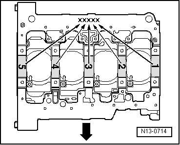
→ fig. 1    Upper crankshaft bearing identification (gradual introduction)

In the factory the upper bearing caps are allocated with the correct thickness for the cylinder block. Coloured marks are used to identify the thickness of the bearing shells => Page 13-36.

Which thickness of shell should be fitted to which location is marked by a letter on the lower sealing surface of the cylinder block -x-.

Arrow indicates direction of travel (forwards).

Colour markings > < Removing and installing drive plate