volkswagen Workshop Repair Guides

Volkswagen Workshop Service and Repair Manuals

Removing and installing fuel gauge sender > < Rules for cleanliness
4cyl. Injection Engine, (2.0 ltr. Engine) (Mexico)
Removing and installing parts of fuel supply system
Removing and installing fuel delivery unit
 
W00-0427

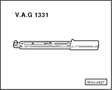
Special tools, workshop equipment, testers, measuring instruments and auxiliary items required

  • ◆ V.A.G 1331 Torque wrench (5 ... 50 Nm)

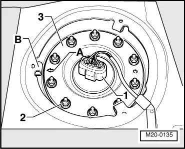
Removing

Prerequisites

  • ● The fuel tank must be empty

Notes:

  • ◆ Observe safety precautions before starting work .
  • ◆ Fuel extraction unit VAS 5190 is recommended for emptying fuel tank. Contrary to the operating instructions the draining must not occur via the filler neck in this engine/vehicle, otherwise inner components will be damaged. Drain fuel tank only via the opened flange.
Warning:
Fuel supply lines are under pressure! When disconnecting the connectors wear eye protection and fuel-resistant gloves. Release pressure by carefully pulling connector off connection.
  • ‒ First check whether a coded radio is fitted. If this is the case obtain the anti-theft coding.
  • ‒ With the ignition switched off disconnect the battery earth strap.
  • ‒ Fold rear seat bench forwards.
  • ‒ Remove cover from fuel delivery unit.
 
M20-0135
  • ‒ → Pull 4-pin connector -1- off.
  • ‒ Unscrew nuts -2- and take flange -3- off.
 
M20-0137
  • ‒ → Disconnect connector-1-.
  • ‒ Remove seal -2-.
  • ‒ Drain fuel tank via flange opening, e.g. with VAS 5190.
 
M20-0142

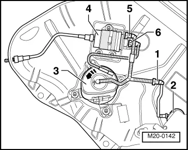
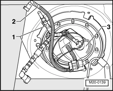
→ Note:

For ease of illustration, the fuel tank upper shell is not shown. The components are shown simplified.

  • ‒ Separate connector -1- on the wiring to the suction jet pump -2-. To do this press safety ring on connector in.
 
M20-0142
  • ‒ → Turn fuel delivery unit -3- in anti-clockwise direction (approx. 45°), take it out of the bayonet joint and place to side.

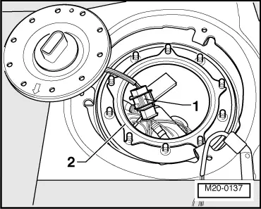
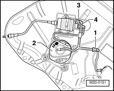
Note:

Observe that the strainer filter and the fuel gauge sender are not damaged.

  • ‒ Remove fuel return hose -6- first from the fuel filter and then the supply hose -5-.
 
M20-0139
  • ‒ → At first take out the supply pipe -1- of the flange cut -out and then the return hose -2-, and after this carefully take out the fuel supply unit -3-.

Notes:

  • ◆ When removing the fuel supply unit observe that the fuel gauge sender is not damaged.
  • ◆ If the fuel delivery unit is to be renewed then drain old fuel delivery unit before disposal.

Installing

 
M20-0151

Installation of the fuel delivery unit is performed in reverse order. When doing this note the following:

  • ‒ → Connect connectors -1-, -3- and -4- (outer supply pipe -3-, return hose -4- centre of fuel retainer).

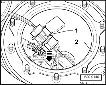
Note:

The supply and return hose connectors must audibly engage. Check for correct seat by tightening.

  • ‒ Turn the fuel delivery unit -2- in the bayonet joint to right onto limit stop.
 
M20-0140
  • ‒ → Fit new seal -2- with the bulge facing the fuel tank.
  • ‒ Place the connector -1- in direction of arrow against the fuel gauge sender behind the fuel supply unit.

Note:

The working area of the float must not be reduced.

 
M20-0135
  • ‒ → Fit locking device -3- so that the arrow -A- is parallel to the vehicle longitudinal axle and shows backwards -B-.
  • ‒ Tighten nuts -2- in a diagonal sequence.
  • Torque setting: 7 Nm
  • ‒ Fit 4-pin connector -1-.
  • ‒ Adapting (matching) engine control unit to throttle valve control part => page 24-43Adapting components and functions.
  • ‒ If the fault memory has been erased or the engine control unit was disconnected from permanent positive, the readiness code must be generated again => page 24-43, Adapting components and functions.

Removing and installing fuel gauge sender > < Rules for cleanliness