
Golf Mk4
|

| 1 - | O-ring |
| q | Renew if damaged. |
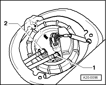
| 2 - | Gravity valve |
| q | To remove valve unclip upwards out of support. |
| q | Check valve for through-flow |
| q | Valve vertical: open |
| q | Valve tilted 45 °: closed |
| 3 - | Breather line |
| q | White. |
| q | Check for secure seating. |
| q | Secure with spring-type clips. |
| q | To activated charcoal filter → Item. |
| 4 - | Cap |
| q | With securing clip |
| 5 - | Seal |
| q | Renew if damaged. |
| 6 - | Securing bolt |
| 7 - | Tank flap unit |
| q | With rubber cup. |
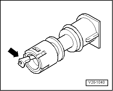
| 8 - | Breather valve |
| q | To remove valve unclip sideways out of support. |
| q | Before installing remove sealing cap → Item. |
| q | Checking → Fig.. |
| 9 - | Earth connection |
| q | Check for secure seating. |
| 10 - | 10 Nm |
| 11 - | Fuel tank filler neck |
| 12 - | Breather line |
| q | Black |
| q | Clipped onto top of fuel tank. |
| q | Check for secure seating. |
| q | Secure with spring-type clips. |
| 13 - | Fuel tank |
| q | When removing, support using engine and gearbox jack -V.A.G 1383 A-. |
| q | Removing and installing → Chapter. |
| 14 - | Clamping washer |
| 15 - | Heat shield |
| q | For fuel tank. |
| 16 - | 25 Nm |
| 17 - | Lock nut |
| 18 - | Fuel tank cover |
| 19 - | Securing strap |
| q | Note differing lengths. |
| q | Installation position: Fixing point (holes) face in direction of travel. |
| 20 - | Supply line |
| q | Black |
| q | Check for secure seating. |
| q | To fuel supply pipe on fuel rail → Chapter. |
| 21 - | Fuel filter |
| q | Installation position: arrow points in direction of flow. |
| 22 - | Screw-type clip |
| q | Note installation position → Fig.. |
| 23 - | Seal |
| q | Renew if damaged. |
| q | When installing, insert seal dry into fuel tank opening. |
| q | Moisten with fuel only when installing flange. |
| 24 - | Fuel delivery unit |
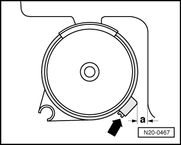
| q | Note installation position of flange on fuel tank → Fig.. |
| q | Removing and installing → Chapter. |
| q | Checking fuel pump → Chapter |
| q | Clean strainer if soiled. |
| 25 - | Union nut, 80 Nm |
| q | Remove and install using union nut tool -3217-. |
| 26 - | Supply line |
| q | Black |
| q | Check for secure seating. |
| q | Clipped onto side of fuel tank. |
| 27 - | Return line |
| q | Blue or with blue marking. |
| q | Clipped onto side of fuel tank. |
| q | Check for secure seating. |
| q | From fuel return pipe on fuel rail → Chapter. |
| 28 - | Overflow hose |
 Note
Note
|
|
Note
|
|

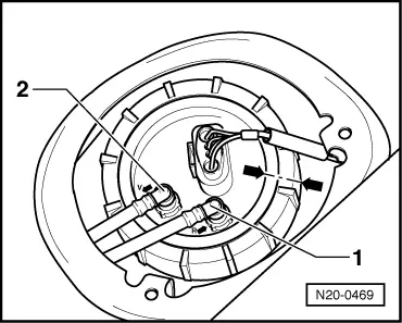
| 1 - | Connector |
| q | Black, 4-pin |
| q | For fuel gauge sender -G- and fuel system pressurisation pump -G6- |
| 2 - | Connector |
| q | Black, 2-pin |
| 3 - | Bracket for return line |
| q | Clipped onto side of fuel delivery unit |
| 4 - | Return line |
| 5 - | Gravity valve |
| q | To remove valve unclip upwards out of support. |
| q | Check valve for through-flow valve vertical: open, valve tilted 45°: closed. |
| 6 - | Breather line |
| q | White. |
| q | Check for secure seating. |
| q | Secure with spring-type clips. |
| q | To activated charcoal filter → Item. |
| 7 - | O-ring |
| q | Renew if damaged. |
| 8 - | Securing clip |
| 9 - | Cap |
| 10 - | Seal |
| q | Renew if damaged. |
| 11 - | Securing bolt |
| 12 - | Tank flap unit |
| q | With rubber cup. |
| 13 - | Breather valve |
| q | To remove valve unclip sideways out of support. |
| q | Before installing remove sealing cap → Item. |
| q | Checking → Fig.. |
| 14 - | Earth connection |
| q | Check for secure seating. |
| 15 - | 10 Nm |
| 16 - | Fuel tank filler neck |
| 17 - | Union nut, 80 Nm |
| q | Remove and install using union nut tool -3217-. |
| 18 - | Fuel gauge sender 2 -G169- |
| q | With suction jet pump: removing, installing and checking suction jet pump → Chapter |
| q | Observe installation position on fuel tank: mark on sender must align with mark on fuel tank |
| q | Checking: → Current flow diagrams, Electrical fault finding and Fitting locations |
| 19 - | Seal |
| q | Renew if damaged. |
| q | When installing, insert seal dry into fuel tank opening. |
| q | Moisten with fuel only when installing flange. |
| 20 - | Breather line |
| q | Black |
| q | Clipped onto top of fuel tank. |
| q | Check for secure seating. |
| q | Secure with spring-type clips. |
| 21 - | Fuel tank |
| q | When removing, support using engine and gearbox jack -V.A.G 1383 A-. |
| q | Removing and installing → Chapter. |
| 22 - | 25 Nm |
| 23 - | Securing strap |
| q | Note installation position. |
| 24 - | Clamping washer |
| 25 - | Heat shield |
| q | For fuel tank. |
| 26 - | Retaining strut |
| 27 - | Supply line |
| q | Black |
| q | Check for secure seating. |
| q | To fuel supply pipe on fuel rail → Chapter. |
| 28 - | Fuel filter |
| q | Installation position: arrow points in direction of flow. |
| 29 - | Screw-type clip |
| q | Note installation position → Fig.. |
| 30 - | Supply line |
| q | Check for secure seating. |
| 31 - | Fuel delivery unit |
| q | With fuel gauge sender -G- |
| q | Note installation position of flange on fuel tank → Fig.. |
| q | Removing and installing → Chapter. |
| q | Checking fuel pump → Chapter |
| q | Clean strainer if soiled. |
| 32 - | Supply line |
| q | Black |
| q | Check for secure seating. |
| q | Clipped onto side of fuel tank. |
| 33 - | Return line |
| q | Blue or with blue marking. |
| q | Clipped onto side of fuel tank. |
| q | Check for secure seating. |
| q | From fuel return pipe on fuel rail → Chapter. |
| 34 - | Overflow hose |
Note
|
|
Note
|
|
Note
|
|