
Golf Mk4
| Dismantling and assembling differential |
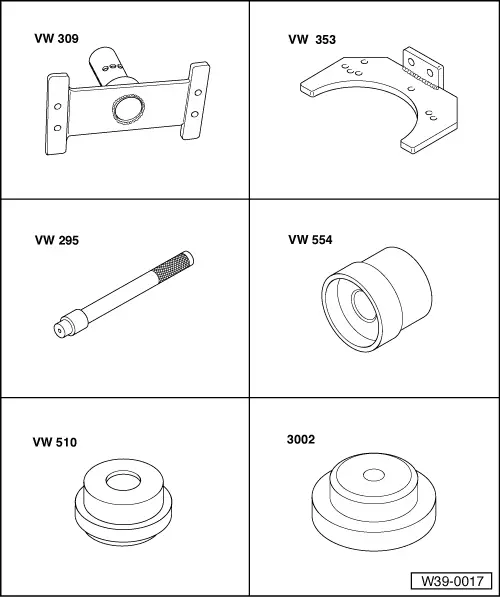
| Special tools and workshop equipment required |
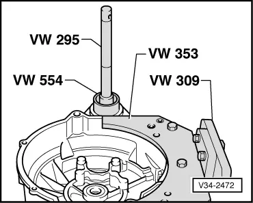
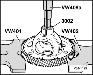
| t | Support plate -VW 309- |
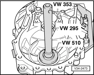
| t | Gearbox support -VW 353- |
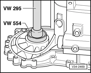
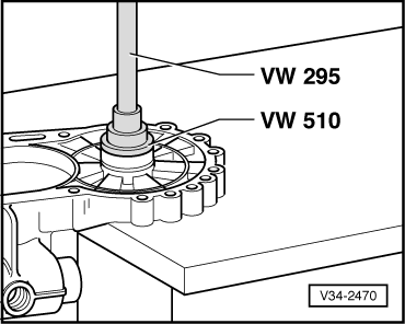
| t | Drift -VW 295- |
| t | Thrust piece -VW 554- |
| t | Thrust pad -VW 510- |
| t | Thrust piece -3002- |
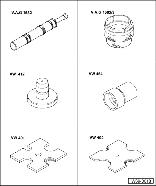
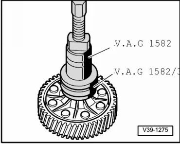
| t | Puller -V.A.G 1582- |
| t | Grip -V.A.G 1582/3- |
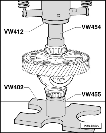
| t | Press tool -VW 412- |
| t | Thrust piece -VW 454- |
| t | Thrust plate -VW 401- |
| t | Thrust plate -VW 402- |
|
|
|
|
|
|
 Note
Note| t | Heat tapered roller bearing inner race to 100° C before installing. |
| t | Always renew both tapered roller bearings together as a set. |
| t | If tapered roller bearings, differential cage, gearbox housing or clutch housing are renewed, adjust differential → Chapter. |
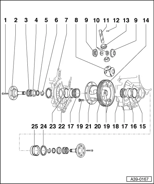
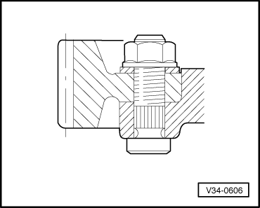
| 1 - | Hexagon socket head bolt, 25 Nm |
| q | Screw into threaded piece → Item. |
| 2 - | Flange shaft |
| q | Removing and installing → Chapter |
| 3 - | Compression spring for flange shaft |
| q | Installed behind flange shafts |
| 4 - | Thrust washer |
| q | Installation position: shoulder faces spring, lugs face tapered ring |
| 5 - | Tapered ring |
| q | With grooves to engage in thrust washer |
| q | Installation position: taper towards differential cage |
| 6 - | Retaining ring |
| q | Holds tapered ring, thrust washer and spring in position when flange shaft is removed. |
| 7 - | Gearbox housing |
| 8 - | One-piece thrust washer |
| q | Coat with gearbox oil when installing |
| 9 - | Large differential bevel gear |
| q | Installing → Fig. |
| 10 - | Threaded piece |
| q | Installing → Fig. |
| 11 - | Differential pinion pin |
| q | Drive out using drift |
| q | Installing → Fig. |
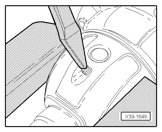
| 12 - | Spring pin |
| q | For securing differential pinion pin |
| q | Removing and installing → Fig.. |
| 13 - | Small differential bevel gear |
| q | Installing → Fig. |
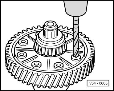
| 14 - | Rivet |
| q | Only in production |
| q | Drilling out → Fig. |
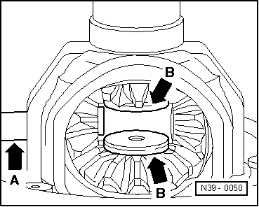
| 15 - | Shim S2 |
| q | Always 1 mm thick |
| 16 - | Tapered roller bearing outer race |
| q | Driving out → Fig.. First remove sleeve ( → Item). |
| q | Driving in → Fig. |
| 17 - | Tapered roller bearing inner race |
| q | Pulling off → Fig. |
| q | Pressing on → Fig. |
| 18 - | Clutch housing |
| 19 - | Repair kit |
| q | Only for Service department. |
| q | Installing → Fig. |
| q | Hexagon nut, 65 Nm |
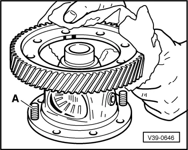
| 20 - | Final drive gear wheel |
| q | Riveted in production. |
| q | Paired with output shaft. Renew only as a set. |
| q | Pressing off → Fig.. |
| q | Installation position → Fig. |
| q | Heat to 100 °C before installing. |
| q | Fit to differential cage → Fig. |
| q | Bolted → Fig.. |
| 21 - | Differential cage |
| 22 - | Tapered roller bearing outer race |
| q | Driving out → Fig. |
| q | Driving in → Fig. |
| 23 - | Shim S1 |
| q | Determining thickness → |
| 24 - | Seal |
| q | Renewing → Chapter |
| 25 - | Sleeve |
| q | To support oil seal. |
| q | Removing and installing → Fig. |
|
|
|
|
Note
|
|
|
|
|
|
Note
|
|
|
|
|
|
|
|
|
|
|
|
|
|