volkswagen Workshop Repair Guides

Volkswagen Workshop Service and Repair Manuals

Torque settings > < Transporting gearbox
Installing gearbox
Installing gearbox
  Note
Refer to procedure „Removing gearbox“ for required special tools → Chapter.
–  All threaded holes into which self-locking bolts are to be screwed must be cleaned of residual locking fluid with a thread chaser.
–  Always renew self-locking bolts and nuts.
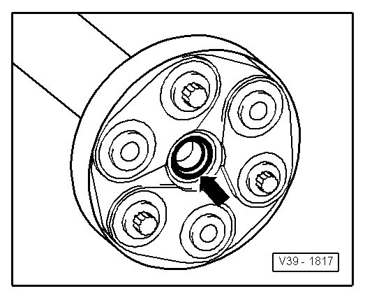
–  Clean input shaft splines and lightly grease with grease -G 000 100-.
The clutch plate must slide easily to and fro on the input shaft.
–  Check whether dowel sleeves for aligning engine and gearbox are fitted in cylinder block and install if necessary.
If dowel sleeves are not fitted, difficulties shifting gears, clutch problems and possible noises from the gearbox (rattling of gears which are not engaged) could occur.
–  Ensure that intermediate plate is correctly seated on engine.
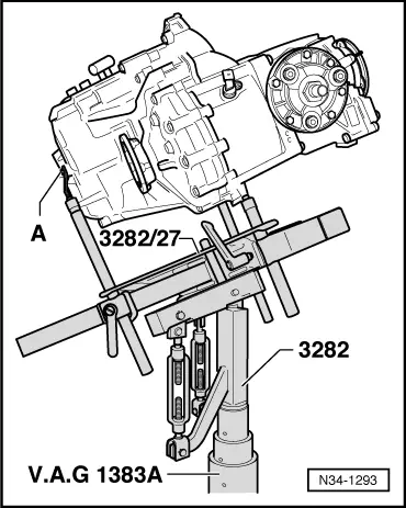
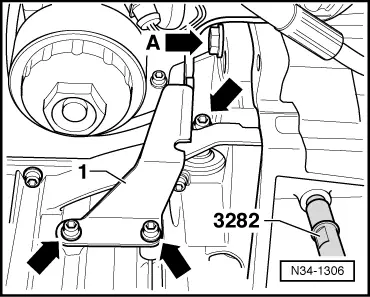
To install gearbox „02M/02Y“, set up gearbox support -3282- with adjustment plate -3282/27-.
–  Align arms of gearbox support according to holes in adjustment plate.
   
–  Attach support elements-A- to adjustment plate as illustrated.
–  Place gearbox on engine and gearbox jack -V.A.G 1383 A-.
–  Align adjustment plate and gearbox parallel to one another.
–  Secure gearbox to gearbox support -3282- using bolt -A-.
  N34-1052
–  Position engine and gearbox jack -V.A.G 1383 A- under vehicle. -Arrow B- on adjustment plate points in direction of vehicle travel.
–  Tilt gearbox to left via spindles of gearbox support -VAS 3282- and turn upwards in vicinity of bevel box.
  N34-1293
–  Then raise gearbox carefully and guide past subframe -arrows-.
–  Have a second mechanic press engine forwards.
  Note
Observe connecting lines and hoses when moving engine.
  N34-1294
–  Guide bevel box past bolting eye -arrow A- and oil pan -2- as shown -arrow B-.
–  Turn gearbox -1- downwards in vicinity of bevel box via spindles of gearbox support -3282- and guide into flywheel (ring gear for starter).
–  Align gearbox to engine and join.
  N34-1307
–  Screw in engine/gearbox connecting bolt -arrow A- and tighten to specified torque → Chapter.
–  Bolt bracket -1- for secondary air pump to engine -arrows- → Rep. gr.26.
–  Install intermediate plate below.
–  Insert lower engine/gearbox securing bolts and tighten to torque specification → Chapter.
–  Carefully raise engine with gearbox. To do this, tighten spindles on support bar -V.A.G 10-222A-.
  N34-1306
–  Install left gearbox bracket -1- using new bolts -arrows- and tighten to specified torque → Chapter.
  N34-1049
–  Position engine and gearbox jack -V.A.G 1383/A- with universal support -V.A.G 1359/2 - under gearbox and raise until gearbox is parallel to gearbox mounting.
–  Align engine and gearbox in installation position.
  N34-1062
–  Screw new hexagon bolts -arrows- for left assembly mounting -2- into bracket -1- and tighten to specified torque → Chapter.
  Note
Use stepladder -VAS 5085- to install securing bolts.
  N34-1048
–  Install new hexagon bolts -arrows- for right assembly mounting in engine bracket → Rep. gr.10.
  Note
Use stepladder -VAS 5085- to install securing bolts.
  WARNING
Do not remove support bracket -10/222A- until the bolts securing the left and right assembly mountings have been tightened to specified torque.
  Note
Install engine and gearbox mounting free of tension → Rep. gr.10.
–  Bolt power assisted steering reservoir to engine mounting.
  A10-0125
–  Install bolt above bevel box -arrow- and tighten to specified torque → Chapter.
  N34-1305
–  Bolt bevel box carrier to engine and bevel box -arrows- → Chapter.
–  Press engine/gearbox assembly towards bulkhead, carefully guiding bevel box pin into propshaft flange.
  Note
  N34-1059
t  When removing and installing gearbox, do not damage seal in the propshaft flange.
t  Renew propshaft if damaged.
t  Ensure that propshaft is horizontal when pushing onto guide pin.
  V39-1817
–  Bolt propshaft with flexible coupling to bevel box flange -arrows- and tighten to specified torque → Item.
–  Attach front exhaust pipe to exhaust manifold → Rep. gr.26.
  V34-2101
–  Install pendulum support -arrows A- and -B- → Running gear, axles, steering; Rep. gr.40.
–  Use new bolts for securing.
–  Attach drive shafts to gearbox → Running gear, axles, steering; Rep. gr.40.
–  Install right drive shaft protective plate.
–  Install radiator fan and, if present additional fan → Rep. gr.19.
–  Install double catalytic converter and reconnect exhaust system → Rep. gr.26.
–  Then install starter and secure with lower bolt → Electrical system; Rep. gr.27.
–  Fit bracket for power assisted steering line to starter and gearbox.
–  Insert upper engine/gearbox securing bolts and tighten to torque specification → Chapter.
  N34-0712
–  Install earth strap at upper engine/gearbox connecting bolt.
  N34-1046
–  Attach connector to speedometer sender -arrow-.
  N34-1041
–  Push pipe/hose line in direction of arrow and press down clamp -arrow-.
–  Remove hose clamp -3094-.
–  Then install upper securing bolt for starter → Electrical system; Rep. gr.27.
  N34-1056
–  Install cable retainer -A- on starter -arrow 3-.
–  Attach connectors for starter -arrow 1- and reversing light -arrow 2-.
  N34-1042
–  Assemble gear selector lever -B--arrow 3-.
–  Tighten hexagon nut -arrow 3- to specified torque → Item.
–  Insert relay lever -A- and secure with securing clip -arrow 2-.
–  Install power assisted steering line -arrow 1-.
  N34-1304
–  Install selector cable support bracket on gearbox and tighten bolts -arrows- to specified torque → Item. If necessary push in hose line on selector cable support bracket.
–  Connect gear selector cable and gate selector cable to respective cable end-pieces.
–  Install battery carrier. → Electrical system; Rep. gr.27.
  N34-1039
–  Install complete air cleaner housing by tightening bolts -4- and -5-.
–  Install intake hose -1-.
–  Attach intake hose -1-, connector -2- and hose -3- to air mass meter → Rep. gr.24.
–  Install battery. → Electrical system; Rep. gr.27.
  A37-0192
–  Push connecting hose -1- for crankcase breather onto cylinder head cover.
–  Push on hose -2- for activated charcoal filter.
–  Push retainer for coolant lines below plenum chamber onto pins -arrows-.
–  Attach earth strap to battery → Electrical system; Rep. gr.27.
  Note
Note radio code for vehicles with coded radio.
–  Check oil in gearbox with bevel box → Chapter.
–  Bleed clutch system → Chapter.
–  Adjust selector mechanism, gearbox with retaining pin (through gearbox date 18 05 3) → Chapter.
–  Adjust selector mechanism, gearbox with angled rod from gearbox date 19 05 3) → Chapter.
–  Install noise insulation. → General body repairs, exterior; Rep. gr.50.
–  Install engine cover.
  N34-1296

Torque settings > < Transporting gearbox