
Golf Mk4
| Repairing clutch housing, from gearbox date 19 05 3 |

| Special tools and workshop equipment required |
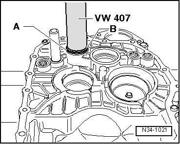
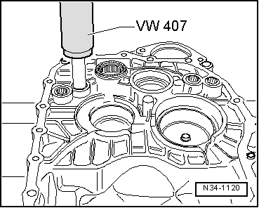
| t | Press tool -VW 407- |
| t | Sleeve -30-21- |
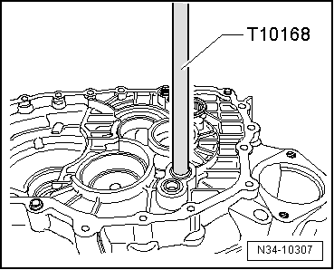
| t | Drift -T10168- |
| t | Thrust piece -T40008- |
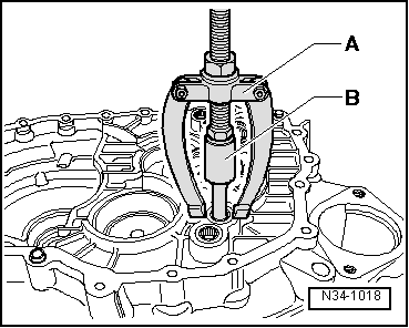
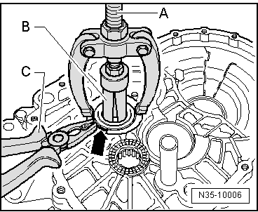
| t | Internal puller -1 - Kukko 21/2- |
| t | Internal puller -1 - Kukko 21/4- |
| t | Counter support -4 - Kukko 22/2- |

| 1 - | Bearing bush |
| q | For selector rods |
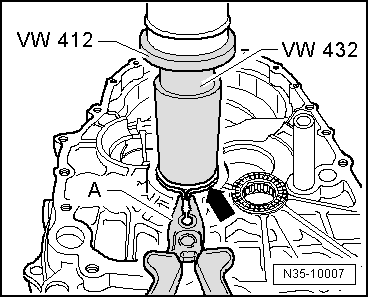
| q | Pulling out → Fig. |
| q | Driving in → Fig. |
| 2 - | Reverse gear selector fork axle |
| q | Axle cannot be removed with workshop tools |
| q | If a new clutch housing is used, a new axle must be pressed in → Fig. |
| 3 - | Needle bearing |
| q | For reverse shaft |
| q | Renew each time after removing |
| q | Pulling out → Fig. |
| q | Pressing in → Fig. |
| 4 - | Dowel sleeve |
| q | Qty. 2 |
| 5 - | Clutch housing |
| q | If renewed: adjust output shafts and differential → Chapter |
| 6 - | Input shaft seal |
| When gearbox is dismantled, oil seal can be removed with sleeve -30-21-. |
| q | Renewing → Item |
| 7 - | Oil guide |
| q | Lever out with a screwdriver |
| q | Fits in one position only |
| 8 - | Washer |
| q | For differential |
| q | Allocation → Electronic parts catalogue (ETKA) |
| q | Installation position: If there is a shoulder on inner circumference, it must face away from outer race of tapered roller bearing → Item |
| 9 - | Tapered roller bearing outer race |
| q | For differential |
| q | Removing and installing → Fig. |
| q | If renewed, adjust differential → Chapter |
| 10 - | Oil deflector ring |
| q | Installation position: shoulder on hole faces output shaft |
| 11 - | Tapered roller bearing outer race |
| q | For output shaft for 1st through 4th gears |
| q | Removing and installing → Chapter |
| q | If renewed, adjust output shaft for 1st through 4th gears → Chapter |
| 12 - | Tapered roller bearing outer race |
| q | For output shaft for 5th, 6th and reverse gears |
| q | Removing and installing → Fig. |
| q | If renewed, adjust output shaft for 5th, 6th and reverse gears → Chapter |
| 13 - | Washer |
| q | For output shaft for 5th, 6th and reverse gears |
| q | Always 0.65 mm thick |
| 14 - | Cylindrical roller bearing |
| q | For input shaft |
| q | Removing and installing → Fig. |
| 15 - | Magnet |
| q | Held in place by housing joint surface |
| 16 - | Cap |
| q | Not fitted in all clutch housings |
|
|
|
|
 Note
Note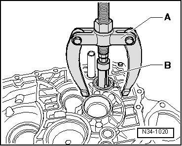
|
|
|
|
|
|
|
|