
Golf Mk4
| Dismantling and assembling output shaft for 1st through 4th gears |

| Special tools and workshop equipment required |
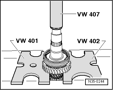
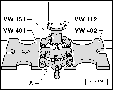
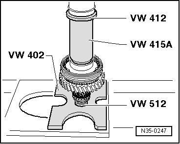
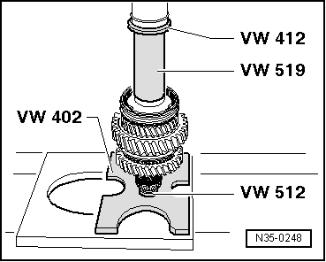
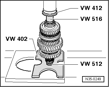
| t | Pressure plate -VW 401- |
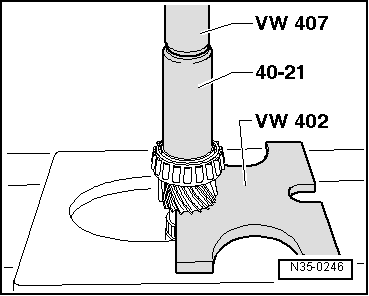
| t | Pressure plate -VW 402- |
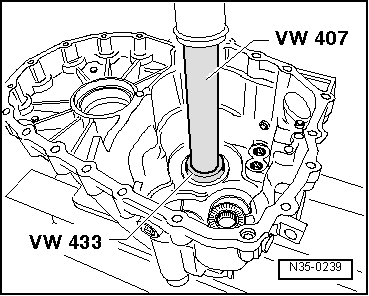
| t | Press tool -VW 407- |
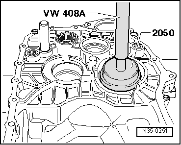
| t | Press tool -VW 408 A- |
| t | Press tool -VW 412- |
| t | Tube -VW 415 A- |
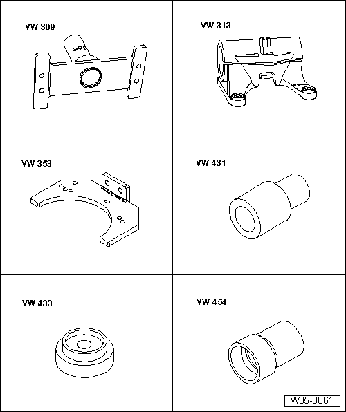
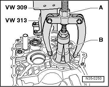
| t | Support plate -VW 309- |
| t | Support clamp -VW 313- |
| t | Gearbox support -VW 353- |
| t | Thrust piece -VW 431- |
| t | Thrust piece -VW 433- |
| t | Thrust piece -VW 454- |

| t | Thrust pad -VW 512- |
| t | Tube -VW 516- |
| t | Tube -VW 519- |
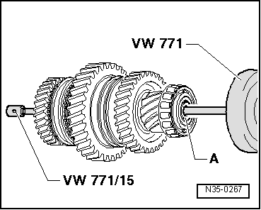
| t | Multipurpose tool -VW 771- |
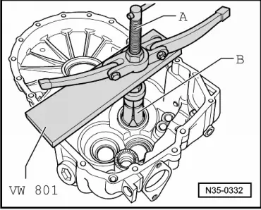
| t | Support plate -VW 801- |
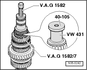
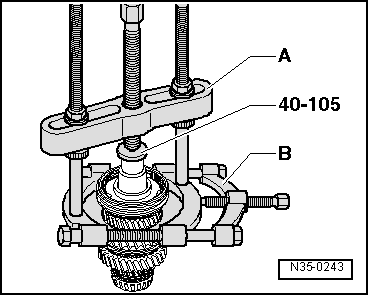
| t | Thrust plate -40-105- |

| t | Drift sleeve -40-20- |
| t | Drift sleeve -40-21- |
| t | Thrust piece -2050- |
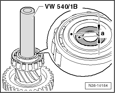
| t | Supplementary set for engine and gearbox support -VW 540/1 B- |
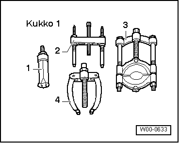
| t | Tapered roller bearing puller -V.A.G 1582- |
| t | Adapter -V.A.G 1582/7- |
|
|
 Note
Note
|
|

| 1 - | Clutch housing |
| 2 - | Oil deflector ring |
| 3 - | Dished washer |
| q | Pulling out → Fig. |
| q | Pressing in → Fig. |
| 4 - | Tapered roller bearing outer race |
| q | Pulling out → Fig. |
| q | Pressing in → Fig. |
| 5 - | Tapered roller bearing inner race |
| q | Pressing off → Fig. |
| q | Pressing on → Fig. |
| 6 - | Output shaft |
| q | For 1st through 4th gears |
| q | Adjusting → Chapter |
| 7 - | Needle bearing |
| q | For 2nd gear |
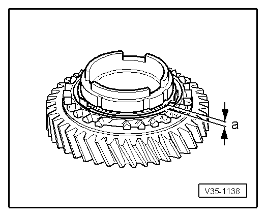
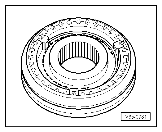
| 8 - | Synchromeshed gear for 2nd gear |
| 9 - | Synchro-ring |
| q | (Inner ring for 2nd gear) |
| q | Check for wear → Fig. |
| q | Check lugs for scoring |
| q | Installation position → Fig. |
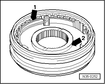
| 10 - | Outer ring for 2nd gear |
| q | Place on synchro-ring → Item |
| q | Renew if scored |
| q | Installation position → Fig. |
| 11 - | Synchro-ring for 2nd gear |
| q | Check for wear → Fig. |
| q | Installation position → Fig. |
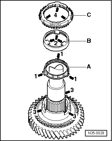
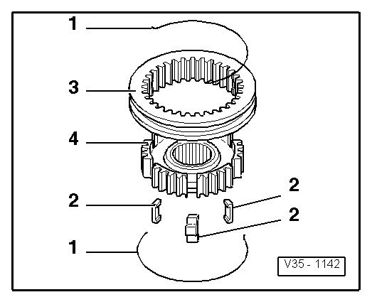
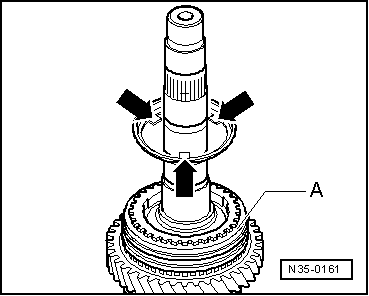
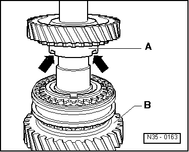
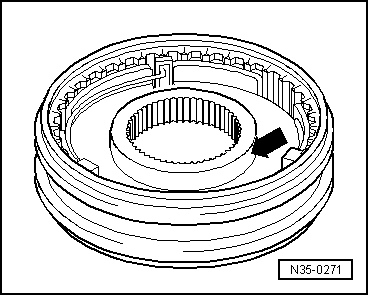
| 12 - | Locking collar with synchro-hub for 1st and 2nd gears |
| q | After removing retaining ring → Item, press off with synchromeshed gear for 2nd gear → Fig. |
| q | Dismantling → Fig. |
| q | Assembling locking collar and synchro-hub → Fig. |
| q | Installation position → Fig. |
| q | Pressing on → Fig. |
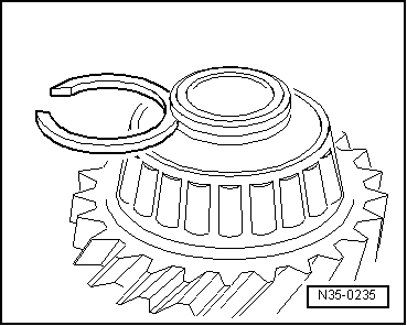
| 13 - | Retaining ring |
| 14 - | Synchro-ring for 1st gear |
| q | Check for wear → Fig. |
| q | Assemble so that notches engage in locking pieces of locking collar → Item |
| 15 - | Outer ring for 1st gear |
| q | Insert in synchro-ring → Item; installation position → Fig. |
| q | Renew if scored |
| 16 - | Synchro-ring |
| q | (Inner ring for 1st gear) |
| q | Check for wear → Fig. |
| q | Check lugs for scoring |
| q | Installation position → Fig. |
| 17 - | Needle bearing |
| q | For 1st gear |
| 18 - | Synchromeshed gear for 1st gear |
| q | Installation position → Fig. |
| 19 - | Thrust washer |
| q | For 1st through 4th gears |
| q | Insert lugs on thrust washer in hole of output shaft. |
| 20 - | Washer |
| q | Holds thrust washers → Item on output shaft. |
| 21 - | Needle bearing |
| q | For 4th gear |
| 22 - | Synchromeshed gear for 4th gear |
| 23 - | Synchro-ring for 4th gear |
| q | Check for wear → Fig. |
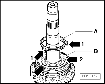
| 24 - | Locking collar with synchro-hub for 3rd and 4th gears |
| q | After removing retaining ring → Item, pull off via 4th gear synchromeshed gear → Item. |
| q | Dismantling → Fig. |
| q | Installation position, locking collar and synchro-hub → Fig. |
| q | Assembling locking collar and synchro-hub → Fig. and → Fig. |
| q | Pressing on → Fig. |
| 25 - | Retaining ring |
| 26 - | Synchro-ring for 3rd gear |
| q | Check for wear → Fig. |
| 27 - | Outer ring for 3rd gear |
| q | Insert in synchro-ring → Item; installation position → Fig. |
| q | Renew if scored |
| 28 - | Synchro-ring |
| q | (Inner ring for 3rd gear) |
| q | Check for wear → Fig. |
| q | Check lugs for scoring |
| q | Installation position → Fig. |
| 29 - | Needle bearing |
| q | For 3rd gear |
| 30 - | Synchromeshed gear for 3rd gear |
| q | Installation position → Fig. |
| 31 - | Tapered roller bearing inner race |
| q | Pulling off → Fig. |
| q | Pressing on → Fig. |
| 32 - | Retaining ring |
| q | If tapered roller bearing → Item and output shaft → Item are renewed, redetermine → Fig. |
| 33 - | Tapered roller bearing outer race |
| q | Pulling out → Fig. |
| q | Pressing in → Fig. |
| 34 - | Shim |
| q | Determining thickness → Chapter |
| 35 - | Gearbox housing |
|
|
|
|
|
|
|
|
|
|
|
|
|
|
|
|
|
|
|
|
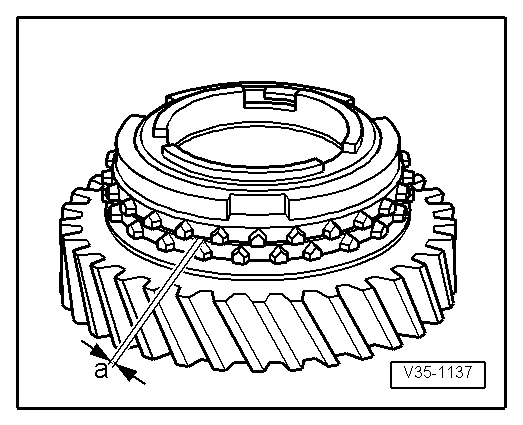
| Gap „a“ | Installation dimension | Wear limit |
| 1st, 2nd and 3rd gears | 0.75 ... 1.25 mm | 0.3 mm |
|
|
| Gap -a- | Installation dimension | Wear limit |
| 1st, 2nd and 3rd gears | 1.2 ... 1.8 mm | 0.5 mm |
|
|
|
|
|
|
|
|
|
|
|
|
|
|
|
|
|
|
|
|
| Gap -a- | Installation dimension | Wear limit |
| 4th gear | 1.0 ... 1.7 mm | 0.5 mm |
|
|
|
|
| Thickness (mm) | ||
| 1.79 | 1.89 | 1.98 |
| 1.83 | 1.92 | |
| 1.86 | 1.95 | |
|
|
|
|