volkswagen Workshop Repair Guides

Volkswagen Workshop Service and Repair Manuals

Checking intake manifold flap motor V157 > < Checking air mass meter G70
Checking intake manifold flap change-over
Engine codes AGR, AHF, ALH
Special tools and workshop equipment required
   
t  
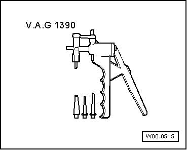
Hand vacuum pump with accessories -V.A.G 1390/-
t  
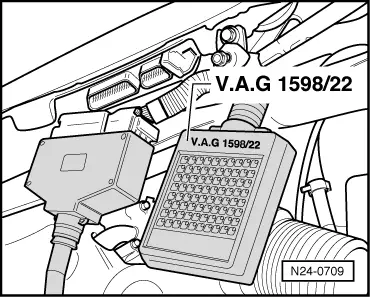
Adapter -V.A.G 1598/22-
t  Hand multimeter -V.A.G 1526C- or multimeter -V.A.G 1715-
t  Adapter set -V.A.G 1594C-
t  Current flow diagram
Checking function
–  Start engine and run at idling speed.
–  Switch off ignition.
–  Observe positioning lever on intake manifold flap (2nd person required).
–  The intake manifold flap must, after switching off ignition, close and after approx. 3 seconds open again.
If change-over does not occur, the following checks must be carried out.
–  Check intake manifold flap change-over mechanics for freedom of movement. To do this, operate rods by hand.
–  Check function of vacuum actuator using hand vacuum pump with accessories -V.A.G 1390/-.
–  Check that vacuum lines are connected correctly.
If no fault is found in the mechanical components:
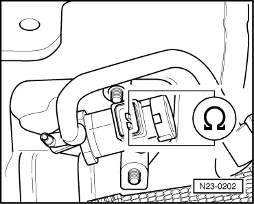
–  Check variable intake manifold flap change-over valve -N239-.
Test procedure
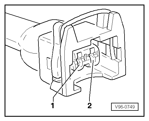
–  Pull connector off variable intake manifold flap change-over valve -N239-.
  W00-0515
–  Measure resistance between change-over valve contacts.
Specification: 25…45 Ω
If the specification is not reached:
–  Renew variable intake manifold flap change-over valve -N239-.
If the specification is attained:
  N23-0202
–  Set multimeter -V.A.G 1715- to measure voltage and connect to contacts 1 + 2 of disconnected connector from intake manifold flap changeover valve -N239-.
–  Start engine and run at idling speed.
Specification: 5...6 V.
–  Switch off ignition.
–  The voltage value must increase to 11...15 V (battery voltage) and after approx. 3 seconds fall to 0 V.
If the voltage values do not change as described:
  V96-0749
–  Connect adapter -V.A.G 1598/22- to control unit wiring harness.
  N24-0709
–  Check wiring between adapter and connector for open circuit using current flow diagram. Contact 1+socket 3 contact 2+socket 2 and 28.
Cable resistance: max. 1.5 Ω.
–  Also check wiring for short to one another, short to vehicle earth and short to battery positive.
Specification: ∞ Ω.
If no fault in lines is detected:
–  Renew diesel direct injection system control unit -J248- → Chapter
  V96-0749

Checking intake manifold flap motor V157 > < Checking air mass meter G70