
Golf Mk4: Motronic Injection and Ignition System (20L) - Fitting Locations
|
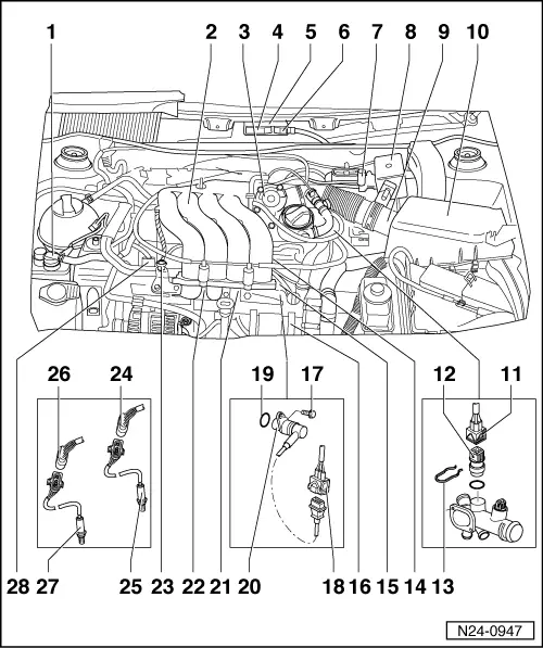
Servicing injection system
Fitting locations overview
|
 |
|
=> Repair group 26; Secondary air system; Removing and installing parts of secondary air system
=> Repair group 26; Secondary air system; Removing and installing parts of secondary air system |
|
|
|
|
|
=> Repair group 26; Secondary air system; Removing and installing parts of secondary air system |
|
|
|
|
|
|