
Golf Mk5
 Note
Note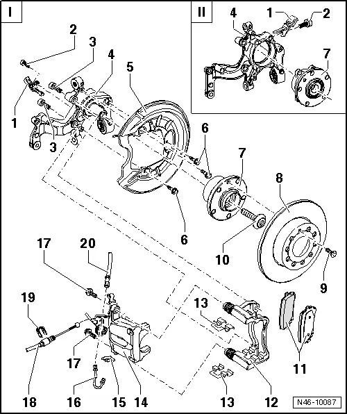
| 1 - | ABS speed sensor |
| q | Before inserting sensor, clean hole inner surface and coat with high-temperature paste G 052 112 A3. |
| 2 - | Hexagon socket head bolt, 8 Nm |
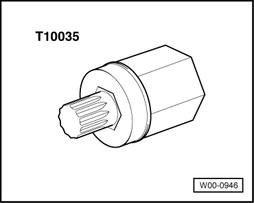
| 3 - | Multi-point socket head bolt, 90 Nm and turn 90° further |
| q | Always renew after removing. |
| q | Remove and install using socket insert -T10035- → Fig.. |
| 4 - | Wheel bearing housing |
| 5 - | Splash plate |
| 6 - | Hexagon bolt, 9 Nm / Torx bolt, 12 Nm |
| q | M6 x 10 hexagon bolt revised to M6 x 12 Torx bolt |
| q | Replace hexagon bolt with hexagon bolt and Torx bolt with Torx bolt |
| 7 - | Wheel bearing/hub unit |
| 8 - | Brake disc |
| q | 15 inches: Ø 260 mm; 16 inches: Ø 286 mm; 17 inches: Ø 310 mm |
| q | Thickness, 15 and 16 inches: 12 mm; 17 inches: 22 mm |
| q | Wear limit, 15 and 16 inches: 10 mm; 17 inches: 20 mm |
| q | When worn, renew on both sides of axle. |
| q | Unscrew brake caliper prior to removing. |
| 9 - | Cross-head screw, 4 Nm |
| 10 - | Bolt |
| q | Front-wheel drive only |
| 11 - | Brake pads |
| q | Thickness: 11 mm not including backplate. |
| q | Wear limit: 2 mm not including backplate. |
| q | Check thickness → Booklet18.1. |
| q | Always renew on both sides of an axle. |
| q | Removing and installing → Chapter. |
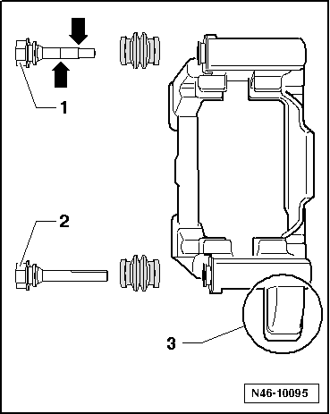
| 12 - | Brake carrier with different guide pins and protective cap |
| q | Supplied as genuine part, assembled with sufficient grease on guide pins. |
| q | If protective caps or guide pins are damaged, install repair kit. Use lubricant sachet supplied to lubricate guide pins. |
| q | Installation instructions → Fig. |
| 13 - | Pad retainer |
| q | Always renew when changing pads. |
| 14 - | Brake caliper |
| q | Do not disconnect brake hose when changing pads. |
| q | Removing and installing → Chapter. |
| q | Repairing → Chapter |
| q | Adjust handbrake cable first after repairing or replacement. |
| q | Adjusting handbrake → Chapter. |
| 15 - | Hose retainer |
| 16 - | Brake line, 14 Nm |
| 17 - | Self-locking hexagon bolt, 35 Nm |
| q | Renew. |
| 18 - | Handbrake cable |
| q | Adjusting handbrake → Chapter. |
| 19 - | Spring clip |
| 20 - | Brake hose |
|
|
|
|