
Golf Mk5
 Note
Note
|
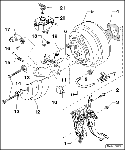
| 1 - | Pedal cluster |
| 2 - | Hexagon bolt, 25 Nm |
| 3 - | Self-locking hexagon nut, 25 Nm |
| q | Always renew after removing. |
| 4 - | Seal |
| q | For brake servo. |
| 5 - | Brake servo |
| q | On petrol engines, the required vacuum is taken from the intake manifold. |
| q | Certain vehicles with a petrol engine and an automatic gearbox are equipped with a brake vacuum pump -V192-. → Chapter |
| q | A vacuum sender is fitted in vehicles with HBV → Chapter. |
| q | Diesel engines are fitted with an vacuum pump to create the required vacuum → Chapter. |
| q | Functional check: |
| – | With engine switched off, depress brake pedal firmly several times. (This will release the vacuum in the unit.) |
| – | Now step on and hold brake pedal with medium pressure and start engine. If the brake servo is functioning properly, the brake pedal will be felt to go down as the servo takes effect. |
| q | If faulty, renew completely (check all vacuum lines first). |
| q | Removing and installing → Chapter. |
| 6 - | Sealing ring |
| 7 - | Brake servo pressure sensor -G294- |
| q | In vehicles with an FSI engine without HBV (hydraulic brake with vacuum servo) |
| q | Removing and installing → Chapter. |
| 8 - | Sealing plug |
| q | Connection for vacuum hose. |
| 9 - | Vacuum hose |
| q | Fit in brake servo. |
| 10 - | Brake servo vacuum sender -G483- |
| q | Only on vehicles having HBV |
| q | Removing and installing → Chapter. |
| 11 - | Brake master cylinder |
| q | With brake light switch -F- from week 45/2005 |
| q | In vehicles prior to week 45/2005, the brake light switch -F- is located on the brake pedal → Chapter. |
| q | Allocation → Electronic Parts Catalogue (ETKA). |
| q | Cannot be repaired. If faulty, renew as a complete unit. |
| q | Removing and installing → Chapter. |
| 12 - | Heat shield |
| 13 - | Hexagon nut, 50 Nm |
| 14 - | Twelve point bolt, 25 Nm |
| 15 - | Brake line, 14 Nm |
| q | From secondary piston circuit of brake master cylinder to hydraulic unit. |
| 16 - | Torx socket head bolt, 5 Nm |
| 17 - | Brake light switch -F- |
| q | Including brake pedal switch -F47-. |
| q | In vehicles prior to week 45/2005, the brake light switch -F- is located on the brake pedal → Chapter. |
| q | Removing and installing → Chapter. |
| 18 - | Sealing plug |
| q | Moisten with brake fluid and press into brake fluid reservoir. |
| 19 - | Brake line, 14 Nm |
| q | From primary piston circuit of brake master cylinder to hydraulic unit. |
| 20 - | Brake fluid reservoir |
| 21 - | Cap |