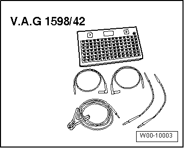
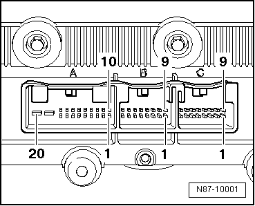
| 16-pin connector, T16d in current flow diagram -C- |
| 1 - | Left temperature flap control motor -V158-, cold |
| 2 - | Left temperature flap control motor -V158-, warm |
| 3 - | Defroster flap control motor -V107-, closed |
| 4 - | Defroster flap control motor -V107-, open |
| 5 - | Central flap control motor -V70-, chest |
| 6 - | Central flap control motor -V70-, footwell |
| 7 - | Vehicles up to week 17/07: air recirculation flap control motor -V113-, recirculated air mode actuation. From calendar week 18/2007: air recirculation flap control motor -V113- was discontinued. |
| 8 - | Vehicles up to calendar week 17/2007: air recirculation flap control motor -V113-, fresh air actuated. From calendar week 18/2007: air recirculation flap control motor -V113- was discontinued. |
| 9 - | Vehicles up to calendar week 17/2007: air flow flap control motor -V71- open. From week 18/07: fresh air/recirculated air, air flow flap control motor -V425- (recirculated air mode/partial air recirculation) |
| 10 - | Vehicles up to calendar week 17/2007: air flow flap control motor -V71- closed. From week 18/07: fresh air/recirculated air, air flow flap control motor -V425- (recirculated air mode/ram air) |
| 11 - | Right temperature flap control motor -V159-, cold |
| 12 - | Right temperature flap control motor -V159-, warm |
| 15 - | Fresh air blower -V2- (PWM actuated) |
| 16 - | Fresh air blower -V2-, feedback signal |
|
|
|