volkswagen Workshop Repair Guides

Volkswagen Workshop Service and Repair Manuals

Installing > < Dismantling and assembling procedure
Removing
Removing
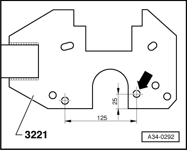
–  First modify gearbox support -3221-.
   
–  Drill a 11.0 mm Ø hole -arrow-.
  A34-0292
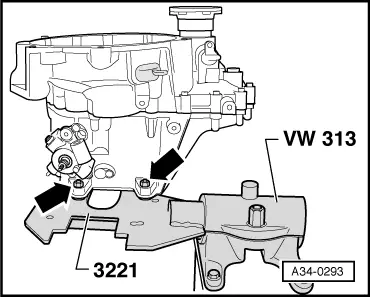
–  Secure gearbox to Gearbox support -3221--arrows-.
–  Place drip tray -V.A.G 1306- underneath.
–  Drain gear oil.
  A34-0293
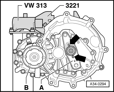
–  Remove clutch release lever -A- together with release bearing and guide sleeve -arrows-.
–  Remove right flange shaft securing bolt -B-.
–  Screw two bolts into flange and counterhold flange shaft using a lever.
–  Remove flange shaft along with spring, thrust washer and tapered ring.
  A34-0294
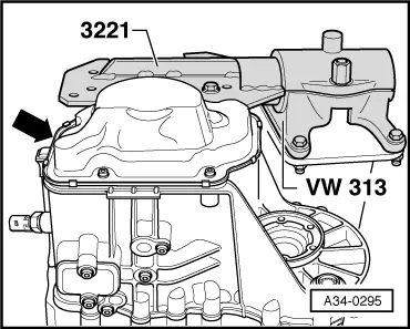
–  Remove gearbox housing cover -arrow-.
  A34-0295
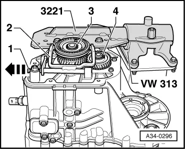
–  Pull out pivot pin -1- for 5th gear -2- and remove selector fork.
–  Remove securing clip -3- for 5th gear synchro-hub.
–  Remove retaining ring -4- for 5th gear wheel.
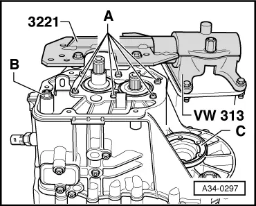
–  Remove bearing mounting securing bolts -A- from input and output shafts.
  A34-0296
–  Remove 5th gear synchro-hub and 5th gear wheel.
–  Unscrew hexagon collared nut -B- for securing reverse gear selector mechanism.
–  Remove flange shaft securing bolt by screwing two bolts into flange and counterholding flange shaft with a lever.
–  Pull out flange shaft -C- with spring.
–  Turn gearbox in support bracket so that clutch housing is upwards.
–  Remove securing bolts from clutch housing side for securing clutch housing to gearbox housing.
–  Remove clutch housing, if necessary carefully levering up all around along protruding housing flange and alternating between sides, being careful not to damage sealing surfaces.
–  Do not cant the clutch housing. This prevents damage to roller bearings and their bearing seats on the input and output shafts.
  A34-0297
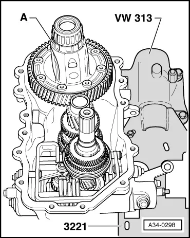
–  Remove differential -A- from gearbox housing.
  A34-0298
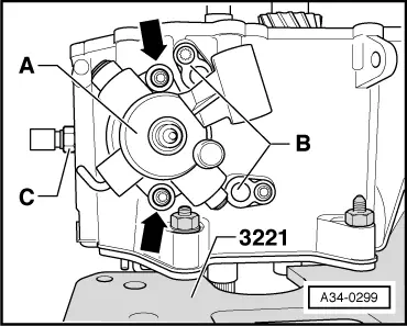
–  Remove selector shaft with selector cover -A-. Place selector shaft in neutral. Then remove bolts -arrows- and pull selector shaft out of gearbox housing.
–  Remove pivot pins -B- located on underside of gearbox.
–  Screw out reversing light switch -F4--C-.
  A34-0299
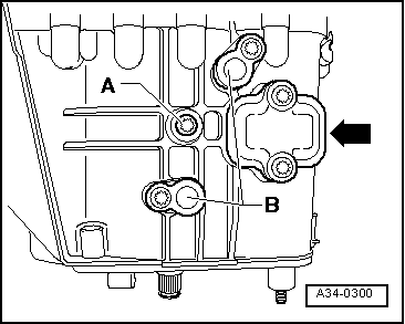
–  Remove bolt -A- for securing reverse gear wheel shaft.
–  Remove pivot pins -B- located on bottom of gearbox.
  Note
Do not remove sealing cover -arrow- when dismantling gearbox.
  A34-0300
–  Press out input shaft, output shaft with bearing mounting, selector mechanism (selector forks) and reverse gear together.
  Note
t  Position gearbox housing so that dowel sleeves in the gearbox will not be damaged.
t  When pressing out, get help from second mechanic to ensure components do not fall out.
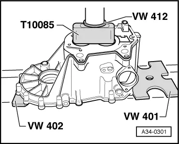
–  Press input shaft and output shaft off bearing mounting with deep groove ball bearing → Fig..
  A34-0301

Installing > < Dismantling and assembling procedure