
Golf Mk5
|
|
|
|
|

|

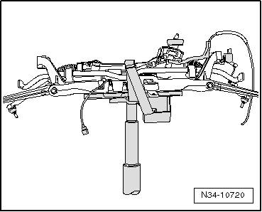
| Special tools and workshop equipment required |
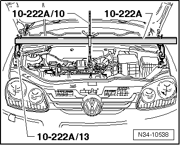
| t | Support bracket -10-222A- |
| t | Adapter -10-222A/3- |
| t | Hook- 10-222A/13- |
| t | Gearbox support -3282- |
| t | Adjustment plate -3282/42 A- |
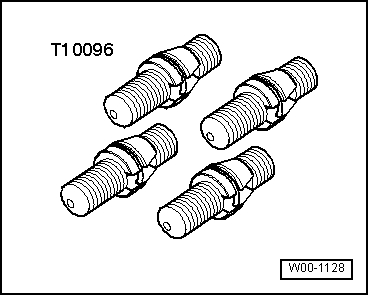
| t | Insert tool 18 mm -T10179- |
 Note
Note
|
|
|
|
|
|
|
|
|
|
|
|
|
|
|
|
|
|
|
|
|
|
|