volkswagen Workshop Repair Guides

Volkswagen Workshop Service and Repair Manuals

Installing gearbox > < Removing gearbox, Golf 2004 ? with 147 kW - 2.0 l petrol engine
Removing gearbox, Golf 2004 ►, with 3.2 l - V6 engine (R32 four-wheel drive)
Brief description
The gearbox is removed downwards separately. »From above«
Remove air filter and starter. Wiring harness which comes from »beneath« from subframe must be disconnected so that subframe can later be removed. The coolant hoses must be clamped off. Left subframe mounting is removed and engine and gearbox supported.
»From below«:
   
Remove -subframe- together with -pendulum support- and -both suspension links- and -steering-.
For information on how to remove the -subframe-, refer to → Rep. gr.40. If the job is done correctly, the subframe can be removed and reinstalled without subsequently causing increased tyre wear, which may lead to customer complaints. It is recommended to read this information »before« removing gearbox. Then the position of the -subframe- can be properly fixed and the subframe removed.
If the position of the subframe was not fixed, the wheels must now be aligned.
After the subframe has been removed, the engine and gearbox must be supported and the left assembly mounting must be separated. Then the »last« connecting bolt between the engine and gearbox must be removed and the gearbox lowered.
  N34-10720
Special tools and workshop equipment required
t  If no hose clamps to 40 mm -3093- are available, use hose clamps to 25 mm -3094-.
t  Insert tool 18 mm -T10179-
t  Ball joint puller -3287 A-
t  Locking device -T10096-
t  Support bar -10 - 222 A- with hook -10 - 222 A /10-
t  Adapter -10 - 222 A /18-

Special tools and workshop equipment required
   
t  Assembly tool -T10071-
  W00-1189
t  Bracket -T10338-
  W00-10410
t  Adjustment plate -3282/42 A-
  W00-10461
t  Adapter -10 - 222 A /18-
Removing:
–  Raise vehicle. All 4 supports of lifting platform must be at same height.
–  Move selector lever to position »P« position.
–  Disconnect battery → Rep. gr.27.
  Note
After loosening central bolt, do not lower vehicle to ground again.
  W00-1209
–  Depress brake pedal to remove bolt for left drive shaft -arrow- (second mechanic required).
–  Remove complete air filter housing → Rep. gr.24, and remove retaining plate beneath that.
  N37-10425
–  Remove starter → Electrical system; Rep. gr.27.
It is advisable to remove the »lower« bolt first.
  N34-10681
–  Remove selector lever cable from gearbox.
Use pliers to remove the washer on the cable support bracket. Do not use a sharp-edged lever, as the rubber grommet on the cable could be damaged.
  N34-10721
Both securing clips must be later renewed when cable is adjusted.
Remove cable with great care from cable support bracket on gearbox. Do not bend it.
Cable may also be pushed slightly backwards out of cable support bracket and removed later when gearbox is lowered. But then observe cable when lowering gearbox.
During later installation, do not clip »small« securing clips on until cable has been checked and adjusted → Chapter.
  N01-0453
–  Clamp off coolant hoses using hose clamps to 40 mm -3093- or hose clamps to 25 mm -3094- and remove.
–  Release mechatronic unit connector by turning and pull off connector.
–  Unbolt wiring retainer from front of »black« gearbox cover (2 nuts M6).
  N34-10215
–  Disconnect -wiring harness- coming »from below« from subframe.
  N34-10722
–  Disconnect wire -1- from electronics box.
  N37-10317
–  Disconnect earth cable -2-.
–  Separate connector -3-.
This wiring harness will later be removed together with the subframe. This will save time-consuming work on the steering and heat shield.
  N37-10318
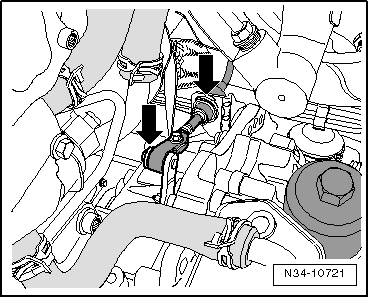
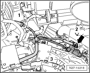
–  Now separate steering from steering column.
Refer to → Running gear, axles, steering; Rep. gr.48 to see what must be done.
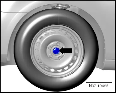
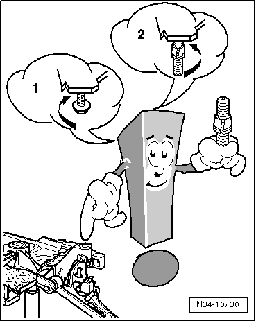
In any case, first return the steering wheel to the straight-ahead position. Engage steering wheel lock. Notes on tightening the bolt can also be found in these instructions.
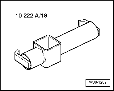
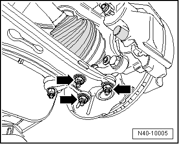
–  Now remove all upper connecting bolts between gearbox and engine. Insert 18 mm -T10179- is especially good for this purpose.
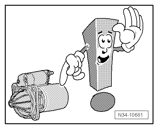
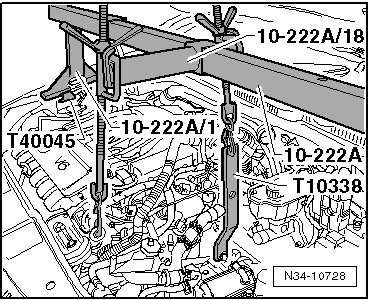
It is advisable to now do all the work which must be done »beneath« the car. This will avoid having the weight of the engine carried by the support bracket and, consequently, by the body, for »a long time«.
–  Remove noise insulation and lower part of front left wheel housing liner → General body repairs, exterior; Rep. gr.66.
  N48-10148
Next remove -subframe- together with -pendulum support- and -both suspension links- and -steering-.
For information on how to remove the -subframe-, refer to → Rep. gr.40. If the job is done correctly, the subframe can be removed and reinstalled without subsequently causing increased tyre wear, which may lead to customer complaints. It is recommended to read this information »before« removing gearbox. Then the position of the -subframe- can be properly fixed and the subframe removed.
If the position of the subframe was not fixed, the wheels must now be aligned.
→ Running gear, axles, steering; Rep. gr.40.
Remove subframe.
  N34-10720
–  First unscrew -nuts- from lower suspension links on both sides.
–  Pull connector off front left vehicle level sender -G78-.
–  Remove both coupling rods from anti-roll bar.
  N40-10005
–  Press off both track rod ball joints.
–  Unbolt pendulum support from gearbox only.
  N48-10011
–  Unbolt bracket for exhaust system -1-.
–  Remove pendulum support bolts -4-.
  N34-10724
Before removing bolts -2- through -5- on both sides, have locating pins -T10096- at hand and support subframe with engine and gearbox support -V.A.G 1383 A-.
  W00-1128
–  After subframe has been supported, remove bolts -2- on both sides.
As soon as bolt -2- has been removed, immediately insert a locating pin -T10096- in the „left and right“ sides.
Do this for bolt -5- also.
If the position of the subframe was not fixed, the wheels must now be aligned.
  N34-10724
Important: remove bolt -1- and immediately install locating pin -2-.
–  Carefully lower subframe, observing wiring harness to engine compartment.
  N34-10730
Set subframe to side.
–  Remove heat shield above right drive shaft.
–  Unbolt both drive shafts from gearbox and carefully lay to side.
–  Remove left drive shaft.
The surface protection of the shafts must not be damaged. Plastic cable ties or a pair of securing straps -T10038- are therefore very good for this.
–  Unbolt propshaft from gearbox.
  N34-10720
The -seal- in the propshaft must not be damaged.
  V39-1817
–  Therefore, clamp assembly tool -T10071- tight with a cloth. This »protects« the ring.
  N34-10726
–  Remove bracket -A- between cylinder block and bevel box.
–  If necessary, remove bracket with secondary pump and lay to side with pump.
–  Remove all connecting bolts but one between engine and gearbox.
It is advisable to leave an easily accessible bolt installed.
–  Remove filler pieces from upper edges of both wings.
–  If there are hoses and cable connections in area of engine support eyes for support bracket -10-222A-, remove these now.
  A37-0655
–  Support engine and gearbox with support bracket -10 - 222 A- and hooks -10 - 222 A /10-. Do not raise.
–  Move »long« spindle on adapter -10 - 222 A /18- forwards.
  N34-10728
–  Remove all bolts -1- and -2- for bracket -A-.
–  Then lower engine and gearbox slightly using spindles of support bracket -10 - 222 A- so that bracket -A- can be removed.
  A37-0653
Remove bracket -arrow-.
Lower only slightly. As soon as the bracket can be removed, the space is sufficient to later guide the gearbox past the longitudinal member. Turn each spindle a maximum of 4 additional turns.
–  Set up gearbox support -3282- with adjustment plate -3282/42 A-.
–  Move engine and gearbox jack -V.A.G 1383 A- under gearbox and support gearbox. Do not raise.
The gearbox is separated from the engine in this position.
–  Remove remaining engine/gearbox connecting bolts.
–  Press gearbox off engine, »observing selector lever cable« and lower gearbox.
Transporting gearbox and securing to assembly stand → Chapter.
Installing gearbox → Chapter.
  N34-10436

Installing gearbox > < Removing gearbox, Golf 2004 ? with 147 kW - 2.0 l petrol engine