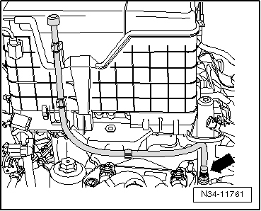
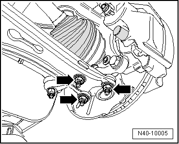
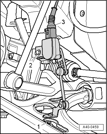
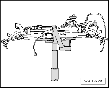
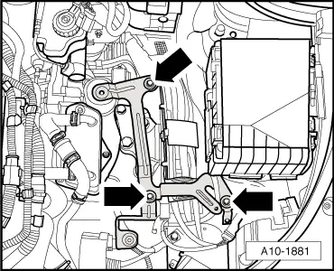
| Next remove -subframe- together with -pendulum support- and -both suspension links- and -steering-. |
| For information on how to remove the -subframe-, refer to → Rep. gr.40. If the job is done correctly, the subframe can be removed and reinstalled without subsequently causing increased tyre wear, which may lead to customer complaints. It is recommended to read this information »before« removing gearbox. Then the position of the -subframe- can be properly fixed and the subframe removed. |
| If the position of the subframe was not fixed, the wheels must now be aligned. |
|
|
|


 Note
Note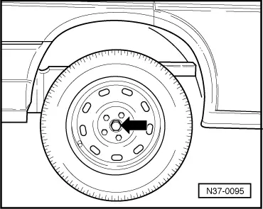
 Caution