
Golf Mk5
| Front-wheel drive - dismantling and assembling differential |

| Special tools and workshop equipment required |
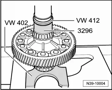
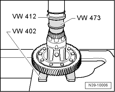
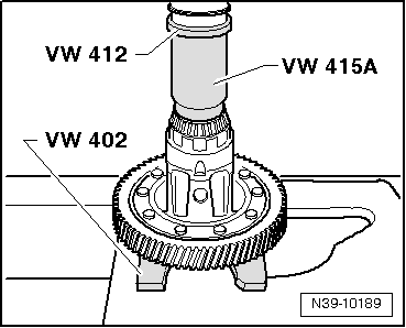
| t | Pressure plate -VW 402- |
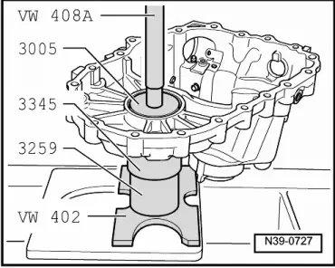
| t | Press tool -VW 408 A- |
| t | Press tool -VW 412- |
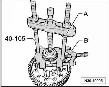
| t | Thrust plate -40-105- |
| t | Thrust plate -3005- |
| t | Only gearboxes with right stub shaft |
| t | Thrust piece -VW 473- |
|
|
|

| t | Tube -3259- |
| t | Tube -3296- |
| t | Tube -3345- |
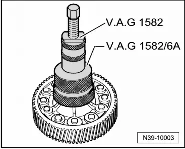
| t | Tapered roller bearing puller -V.A.G 1582- |
| t | Adapter -V.A.G 1582/6A- |
| t | -1-Internal puller -Kukko 21/7- |
| t | -2-Puller -Kukko 18/1- |
| t | -3-Splitter -Kukko 17/1- |
| t | -4-Counter support -Kukko 22/2- |
 Note
Note| t | Heat tapered roller bearing inner race to 100 °C before installing. |
| t | Always renew both tapered roller bearings together as a set. |
| t | If tapered roller bearings, differential cage, gearbox housing or clutch housing is renewed, adjust differential → Chapter. |

| 1 - | Gearbox housing |
| 2 - | Shim |
| q | For differential |
| q | Determining thickness → Chapter |
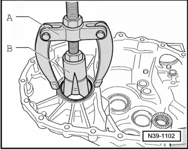
| 3 - | Tapered roller bearing outer race |
| q | Pulling out → Fig. |
| q | Pressing in → Fig. |
| 4 - | Tapered roller bearing inner race |
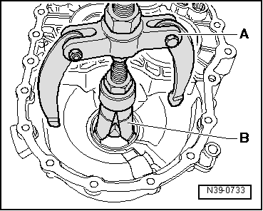
| q | Pulling off → Fig. |
| q | Pressing on → Fig. |
| 5 - | Differential cage |
| q | With riveted final drive gear |
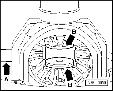
| q | Support -arrow- for right tapered roller bearing 12.5 mm longer beginning with introduction of right flange shaft. |
| Allocation → Electronic parts catalogue „ETKA“ |
| 6 - | Tapered roller bearing inner race |
| q | Pulling off → Fig. |
| q | Gearbox with right stub shaft: pressing on → Fig. |
| q | Gearbox with right flange shaft: pressing on → Fig. |
| 7 - | Tapered roller bearing outer race |
| q | Pulling out → Fig. |
| q | Pressing in → Fig. |
| 8 - | Washer |
| Installation position: shoulder on inner circumference faces clutch housing |
| Allocation → Electronic parts catalogue „ETKA“ |
| 9 - | Clutch housing |
| 10 - | O-ring |
| q | Always renew |
| 11 - | Protective ring |
| q | Can be pulled off or pushed onto stub shaft → Item by hand |
| 12 - | Countersunk bolt, 33 Nm |
| q | Screw into threaded piece → Item |
| 13 - | Stub shaft |
| q | From gearbox date 01 11 4, replaced with a flange shaft → Item |
| Allocation → Electronic parts catalogue „ETKA“ |
| 14 - | Seal |
| q | Through gearbox date 31 10 4, for stub shaft |
| q | Renewing with gearbox installed → Chapter |
| 15 - | Right flange shaft |
| q | Replaces stub shaft from gearbox date 01 11 4 → Item |
| Allocation → Electronic parts catalogue „ETKA“ |
| 16 - | Protective ring |
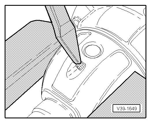
| q | Pry protective ring off flange shaft with a screwdriver, alternating sides → Item |
| q | Push on protective ring to stop by hand |
| q | Protective ring must engage in flange shaft |
| 17 - | Seal |
| q | For flange shaft from gearbox date 01 11 4 → Item |
| q | Renewing with gearbox installed → Chapter |
| Allocation → Electronic parts catalogue „ETKA“ |
| 18 - | Compression spring for flange shaft or stub shaft |
| q | Installed behind flange shaft or stub shaft |
| 19 - | Thrust washer |
| q | Installation position: shoulder faces spring, lugs, if present, face tapered ring |
| 20 - | Tapered ring |
| q | Installation position: taper towards differential cage |
| 21 - | Retaining ring |
| q | Holds tapered ring, thrust washer and spring in position when flange shaft or stub shaft is removed |
| 22 - | Large differential bevel gear |
| q | Installing → Fig. |
| 23 - | Differential pinion pin |
| q | Drive out using drift |
| q | Installing → Fig. |
| 24 - | Spring pin |
| q | For securing differential pinion pin |
| q | Removing and installing → Fig. |
| 25 - | Small differential bevel gear |
| q | Removing and installing → Fig. |
| 26 - | Threaded piece |
| q | Installing → Fig. |
| 27 - | One-piece thrust washer |
| q | Coat with gear oil when installing |
| 28 - | Protective ring |
| q | Pry off protective ring using screwdriver on alternate sides |
| q | Install with indentation facing away from threaded hole in flange shaft |
| q | Push on protective ring to stop by hand |
| q | Protective ring must engage in flange shaft |
| 29 - | Flange shaft |
| 30 - | Seal |
| q | For flange shaft |
| Allocation → Electronic parts catalogue „ETKA“ |
| q | Renewing with gearbox installed → Chapter. |
Note
|
|
Note
|

|
|
|
|
|
|
|
|
|
|
|
|
|
|
|
|
|