volkswagen Workshop Repair Guides

Volkswagen Workshop Service and Repair Manuals

Installing > < Assembly order: I = gearbox »with« circlip A for input shaft cover made from sheet metal; II = gearbox with input shaft cover ma
Removing
Removing
–  Secure gearbox to assembly stand using bolts -arrows-.
  Note
   
If one of the bolting holes does not contact the gearbox support, lay a washer between the hole and the gearbox support.
–  Rotate gearbox on assembly stand so that oil drain plug is below.
–  Place drip tray underneath.
–  Drain gear oil from gearbox.
  N34-10023
Gearbox for four-wheel drive
–  Remove right flange shaft countersunk bolt with socket.
–  Remove the 4 connecting bolts -arrows- for bevel box to gearbox (only 3 are visible in figure).
–  Carefully press bevel box off gearbox, taking care that it does not fall.
Gearbox for front-wheel drive
  A34-10040
–  Remove right flange shaft (fig. shows left flange shaft).
Continuation for all
  A39-0360
–  Remove slave cylinder with clutch release bearing -arrows-.
  N34-0995
–  Remove bolts -B-, which secure gearbox housing to clutch housing.
  Note
One bolt -arrow- is located outside of bolting flange.
–  Lock input shaft.
The lengths of the splines on the input shaft differ to those of the gearbox.
  N34-0997
–  Set either installing sleeve -VW 455- over input shaft on clutch housing
  N34-10025
–  or set sleeve -3160- over input shaft on clutch housing
–  Clamp splitter-A-, e.g. -Kukko 17/0-, behind notch in splines of input shaft.
The back side of the splitter must rest against installing sleeve -VW 455- or sleeve -3160- without play.
  N34-11206
–  Remove left flange shaft.
  A39-0360
–  Gearboxes for vehicles with start-stop system: remove gearbox neutral position sender -G701--arrow-.
  N34-11292
During the following steps, ensure that the selector shaft is not blocked by the angled rod -arrow-.
–  Move selector shaft to neutral.
–  Remove locking bolt -2-.
–  Then remove bolts -3-.
–  Remove reversing light switch -F4--1-.
–  Pull selector shaft -4- out of gearbox housing.
  N34-10024
Sheet metal cover plate
–  Remove retaining ring -A- for input shaft sealing cover.
  N34-11100
–  Pierce rubber in centre of cover -C- with a screwdriver.
–  Pull sealing cover out of gearbox housing.
A - Counter support, e.g. -Kukko 22/1-
B - Internal puller, 8 … 12 mm, e.g. -Kukko 21/01-
  N34-10026
Plastic cover plate
Carefully remove all lugs -A-. When doing this, do not damage gearbox housing.
  N34-11628
–  Lever out cover.
l  Ensure that cover plate components are removed where necessary.
Continuation for all
  N34-11683
Remove retaining ring -C- from deep groove ball bearing of input shaft in gearbox housing as follows:
–  Hold one end of retaining ring with screwdriver-A-.
–  Using a screwdriver, -B-, lever other end out of groove in deep groove ball bearing -direction of arrow-.
–  Using screwdriver-B-, lever out securing ring further.
  N34-10027
–  Remove securing bolts -A- for gearbox housing to clutch housing.
  N34-0923
–  Screw adapter VW 771/40 into threaded hole of gearbox housing.
–  Heat gearbox housing using e.g. hot air blower -V.A.G 1416- in vicinity of bearing seat for deep groove ball bearing for input shaft for about 10 minutes to about 100°C.
–  Using multi-purpose tool VW 771/1, pull gearbox housing off clutch housing in -direction of arrow-.
  Note
If necessary, carefully apply assembly lever on alternating sides at overhanging housing shoulders along perimeter, being careful not to damage sealing surfaces.
  N34-10028
–  Remove splitter-A- and installing sleeve VW 455 or sleeve -3160- from input shaft.
To remove shafts from clutch housing, a second mechanic is required.
  N34-10025
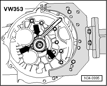
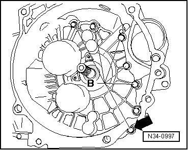
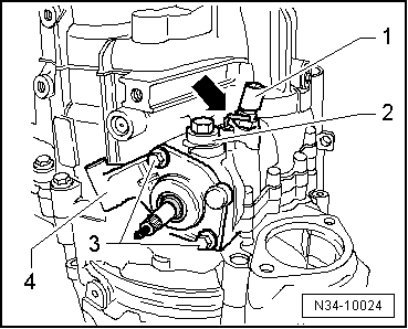
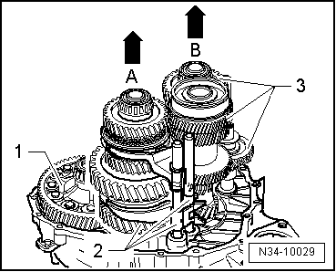
–  With left hand, raise differential -1-. With right hand, lift output shaft for 1st to 4th gear together with selector rods -2--arrow A-.
–  At same time, second mechanic lifts input shaft, reverse shaft and output shaft for reverse, 5th and 6th gears -3- together with selector rods out of clutch housing -arrow B-.
  Note
After shafts are lifted, differential may be set back in clutch housing if desired.
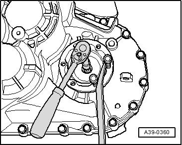
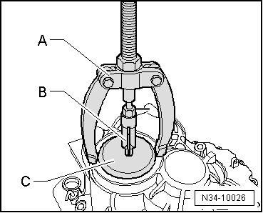
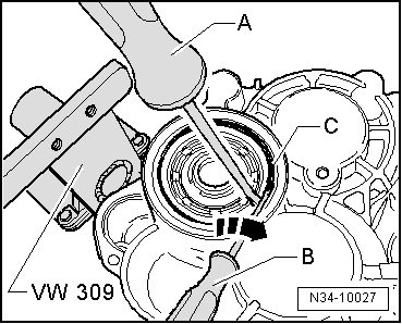
–  Lever out input shaft oil seal using oil seal extractor lever -VW 681-.
  Note
Always renew deep groove ball bearing on input shaft → Item.
  N34-10029

Installing > < Assembly order: I = gearbox »with« circlip A for input shaft cover made from sheet metal; II = gearbox with input shaft cover ma