volkswagen Workshop Repair Guides

Volkswagen Workshop Service and Repair Manuals

Transporting gearbox > < Removing and installing gearbox, Golf 2004 ?
Removing gearbox
Removing gearbox
–  First check whether a coded radio is fitted. If so, obtain anti-theft code.
–  With ignition switched off, disconnect battery earth strap → Electrical system; Rep. gr.27.
At a later point, the support bracket -10 - 222 A- will be connected to the lifting eyes of engine.
–  If engine cover blocks access, remove engine cover.
–  Remove air filter with engine cover if it is located close to the battery → Rep. gr.24.
–  Remove battery, battery cover and battery tray → Electrical system; Rep. gr.27.
   
–  Remove securing clip -3- for gear selector cable from gearbox selector lever -1- and pull cable off pin -arrow-.
Metal relay lever
–  Remove securing clip -4- for gate selector cable from relay lever -2- and pull cable off pin -arrow-.
Plastic relay lever
  N34-10000
Releasing cable end-piece from gate selector cable
l  To avoid damage to gate selector cable, separate cable end-piece from gate selector cable before removal.
–  Pull locking mechanism forwards onto stop in direction of -arrow 1- and then lock by turning anti-clockwise in direction of -arrow 2-.
–  Push relay lever forwards (-direction of arrow 3-).
–  Remove relay lever made from plastic together with cable end-piece as work procedure continues.
Continuation for all
  N34-10891
–  Remove cable support bracket from gearbox -arrows-, lay to side and secure with wire.
  N34-10001
–  If a plastic line is installed, clamp off supply hose to master cylinder using hose clamps up to 25 mm -3094-.
  A30-0127
–  If a pipe/hose line is installed, clamp off hose of pipe/hose line -A- to slave cylinder using hose clamps up to 25 mm -3094-.
–  Pull out clip -arrow- for pipe/hose line or plastic line to stop.
–  Pull pipe/hose line or plastic line out from slave cylinder bleeder and seal.
  Caution
Do not operate clutch pedal any more.
  N34-10002
–  Remove earth strap -1- from top starter bolt.
–  Disconnect electrical connector -2- for reversing light switch -F4-.
–  Remove connector and wire from starter.
  N34-10003
–  Remove upper engine/gearbox connecting bolts -arrows-.
–  Then remove upper securing bolt on starter.
–  Remove foam pieces from upper edge of left and right wings → Body, front; Rep. gr.50.
–  If there are hose and cable connections in area of engine support eye for support bracket -10 - 222 A-, remove these now.
  N34-10701
–  Set up support bracket -10 - 222 A- together with adapters -10 - 222 A /13- and hook -10 - 222 A /10- in front of bonnet gas struts.
–  Attach hook -10 - 222 A /10- in engine support eye.
–  Take up weight of engine/gearbox assembly on spindles.
  Note
  N34-10538
t  Check whether an intermediate shaft -arrow- is installed between right drive shaft -A- and gearbox.
  N34-10539
t  For vehicles with intermediate shaft, with vehicle standing on its wheels, loosen flange bolt -2- for right drive shaft -1- a maximum of 90°. Otherwise, wheel bearing will be damaged → Running gear, axles, steering; Rep. gr.40.
–  Loosen wheel bolts on front left and front right.
–  Raise vehicle.
–  Remove front wheels.
–  Remove noise insulation → General body repairs, exterior; Rep. gr.50.
–  Remove lower part of front left wheel housing liner → General body repairs, exterior; Rep. gr.66.
  A40-0444
–  If present, remove front vehicle lever sender -G78--arrows- → Running gear, axles, steering; Rep. gr.40.
–  Remove bracket from starter.
–  Remove starter → Electrical system; Rep. gr.27.
  A40-0455
–  Separate connection -arrow 1- or -arrow 2- on charge air hose.
  N34-10733
–  Remove exhaust system bracket from subframe -arrows-.
  A26-0719
–  Separate exhaust system at double clamp -arrows-.
–  Tie up front exhaust pipe.
  V26-0733
–  If present, remove support -1- for exhaust system from gearbox -arrow- and front exhaust pipe.
  N34-10006
–  Remove pendulum support from gearbox, bolt -2- and bolt -3-.
–  Pull off connector from sender for oil level and oil temperature -G266-.
–  Disconnect left drive shaft from gearbox flange shaft.
–  Secure drive shafts with wire. When doing this, do not damage surface protection.
  A10-1578
If an intermediate shaft -C- is present, remove right drive shaft -A-. Then remove intermediate shaft from mounting bracket -D--arrows- and pull this off from stub shaft of gearbox.
  N34-10008
If there is no intermediate shaft, separate right drive shaft only from flange shaft -A- of gearbox.
  N34-1849
–  To do this remove drive shaft cover from engine (bolts -1-) → Running gear, axles, steering; Rep. gr.40.
–  Secure drive shaft with wire.
Continuation for all
–  Separate left and right coupling rods from anti-roll bar.
  N17-10184
–  Unscrew nuts -arrows- for swivel joint on suspension links.
–  Fix subframe in position prior to removal → Running gear, axles, steering; Rep. gr.40.
–  Remove subframe with pendulum support, anti-roll bar, brackets and suspension links → Running gear, axles, steering; Rep. gr.40.
  N40-10005
–  Remove hexagon bolts -arrows- on left engine/gearbox mounting -2- from bracket -1-.
  N34-10009
–  Lower gearbox about 60 mm, -a- by adjusting spindles.
  Note
When moving engine and gearbox assembly, observe coolant hose between engine and heat exchanger, being careful not to stretch it.
  A34-0626
–  Remove bracket -1- from gearbox -arrows-.
Metal relay lever
  N34-10010
–  Pull securing clip -arrow- off relay lever -1- and remove relay lever.
Plastic relay lever
–  Removing relay lever together with cable end-piece → Chapter.
Continuation for all
–  Remove selector lever from selector shaft.
  N34-10012
–  Remove engine/gearbox connecting bolt -arrow-.
–  Remove small cover plate -A- for flywheel.
  N34-10357
–  Remove lower engine/gearbox connecting bolts -2-.
  Note
Loosen engine/gearbox connecting bolt -3- and leave it installed just hand-tight.
To remove gearbox „02Q“, set up gearbox support -3282- with adjustment plate -3282/33-.
–  Insert gearbox support -3282- in engine and gearbox jack -V.A.G 1383 A-.
–  Align arms of gearbox support according to holes in adjustment plate.
  N34-10719
–  Attach support elements-A- to adjustment plate as illustrated.
–  Screw in pin -3282/29- instead of support element-C-.
–  Position engine and gearbox jack -V.A.G 1383 A- under vehicle. Arrow -B- on adjustment plate points in direction of vehicle travel.
–  Align adjustment plate parallel to gearbox.
  N34-1332
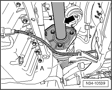
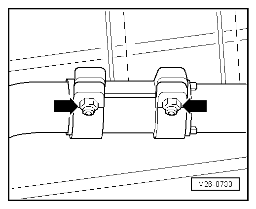
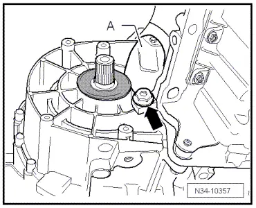
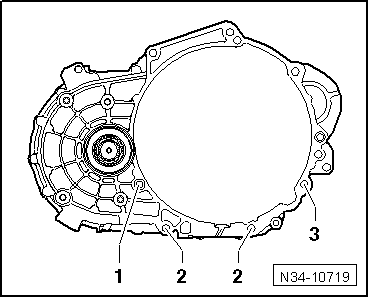
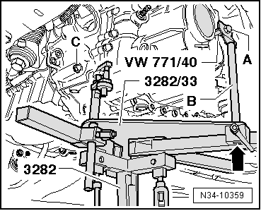
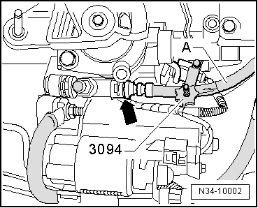
–  Secure adapter -VW 771/40- in threaded hole of gearbox housing as shown in figure.
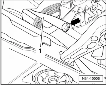
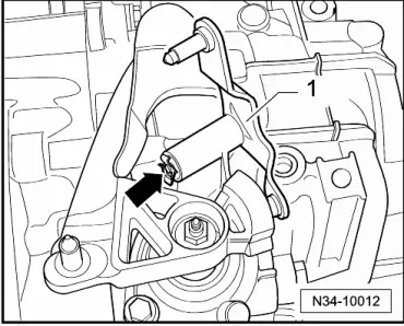
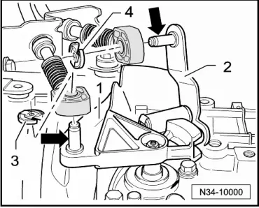
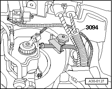
–  Screw pin -3282/29- into hole on gearbox for securing bolt of pendulum support.
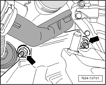
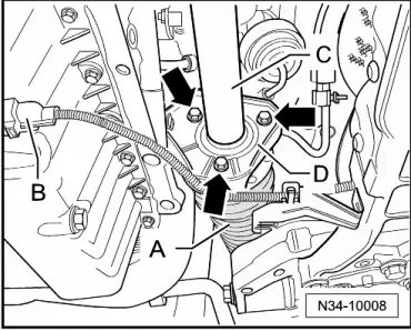
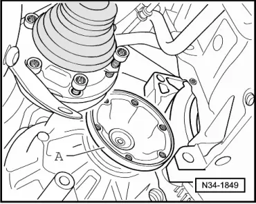
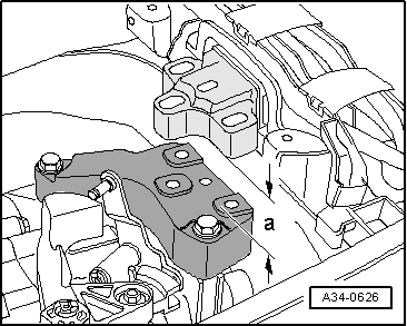
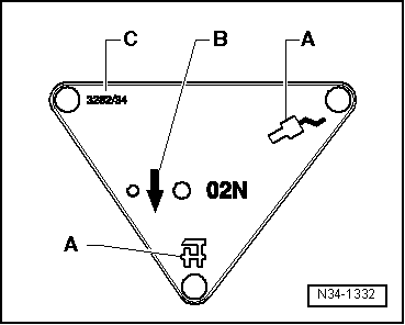
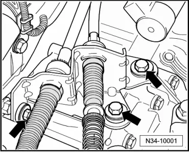
–  Secure gearbox to gearbox support -3282- using bolt (M10x20) -A-.
Pin -B- must lie flush with guide from gearbox support -3282- at bottom -arrow-.
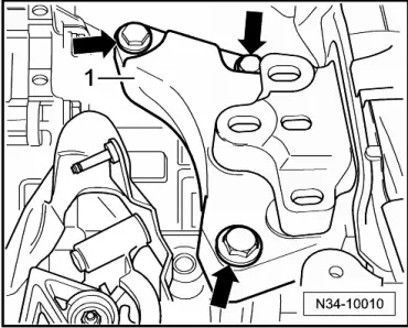
–  Remove last engine/gearbox connecting bolt -C-.
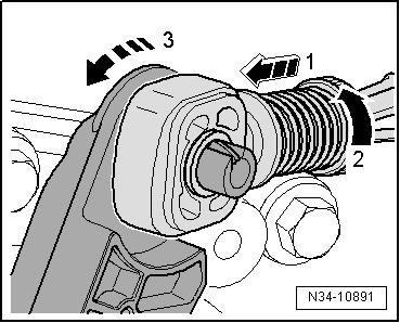
–  Press gearbox away from engine, off dowel sleeves.
–  Raise gearbox near differential via spindle of gearbox support -3282-.
–  Rotate gearbox to left via spindle of gearbox support -3282-.
–  Lower gearbox carefully.
  Note
t  When lowering gearbox, observe, if appropriate, steering box.
t  Be careful of all lines when lowering gearbox.
  N34-10359

Transporting gearbox > < Removing and installing gearbox, Golf 2004 ?