volkswagen Workshop Repair Guides

Volkswagen Workshop Service and Repair Manuals

Installing base plate > < Assembly overview - selector lever and selector housing (from 11.06)
Dismantling and assembling selector mechanism (from 11.06)
   
Dismantling and assembling selector mechanism (from 11.06)
Special tools and workshop equipment required
t  Release tool -T10236-
t  Press tool -VW 412-
t  Assembly tool -T10178-
t  Adapter -10 - 222 A /25-
t  2 = counter support e.g. from -Kukko Baureihe 16-
t  Wedge -T10357-
  W34-10219
thrust piece -T10083-
Dismantling
–  Remove selector mechanism → Chapter.
  W00-1113
–  Bend open tabs -arrows- of base plate for selector mechanism using a screwdriver and remove base plate (only tabs on left side of base plate are illustrated).
–  Remove gasket → Item from selector housing.
–  Remove gear and gate selector cables from selector housing → Chapter.
–  Lift upper end -A- of compression spring over tab of gate selector lever.
  A34-0588
–  Use screwdriver to press catches -arrows- of ball socket towards bearing ball of gear lever guide; break off catches if necessary.
–  Lever ball socket -A- with gear lever guide -B- out of selector housing.
  N34-10921
–  Then press ball socket off bearing ball of gear lever guide and remove it.
l  Please pay attention to guides -A- during the further procedure.
l  They must not be broken off.
–  Lever lower end -arrow 1- of compression spring onto shoulder on gate selector lever as far as stop.
  N34-10922
–  Now pull gear lever guide up to stop and pull ball stud out of gate selector lever -arrow 2-.
  N34-10865
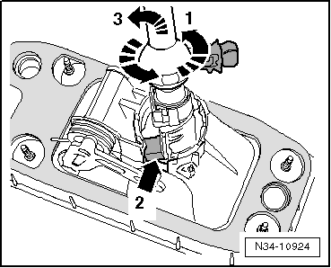
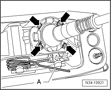
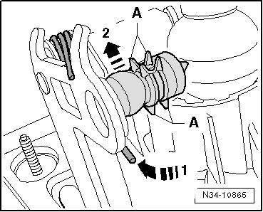
–  Then turn gear lever guide in -direction of arrow 1-.
l  Pin -arrow 2- must be in notch in selector housing
–  Then swing out gear lever guide with gear lever in -direction of arrow 3-.
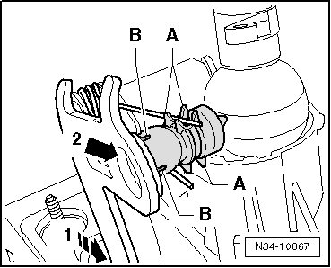
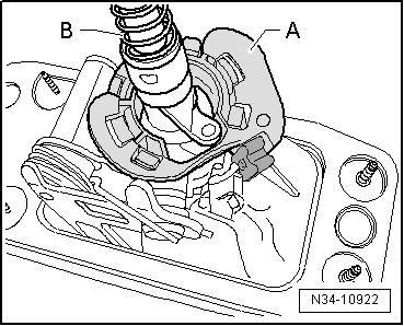
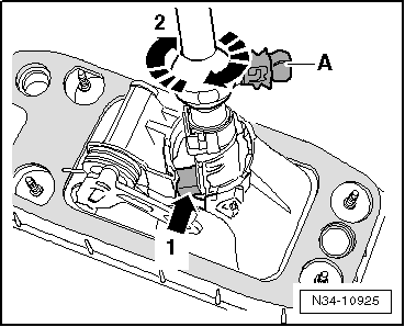
Assembling
  Caution
The lower end of the compression spring (-arrow 1- ⇒ figure above) can snap off the shoulder of the gate selector lever out of control during the further procedure.
–  Therefore, carefully press it down off shoulder of gate selector lever.
The ends of the compression spring then become tensioned „diagonally“ with a loud noise.
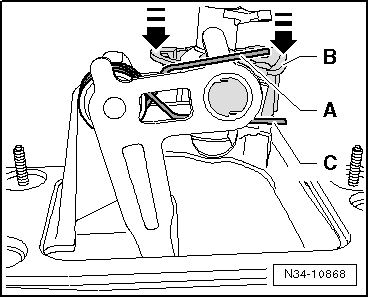
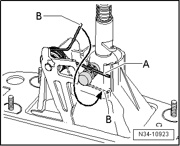
–  Slacken ends -A- and -B- by turning both round to right.
  N34-10924
l  Ends -A- and -B- must point in opposite directions.
  N34-10923
–  Fit gear lever guide in selector housing.
l  Pin -arrow 1- is still located in notch in selector housing.
–  Turn gear lever guide in -direction of arrow 2- until ball stud -A- is located in notch in selector housing.
  N34-10925
–  Place selector housing with gear lever guide into larger recess -arrow- in thrust piece -T10083-.
  N34-10869
l  The gear lever guide must project from the selector housing up to the stop.
–  Insert end -A- of compression spring into guide from above.
–  Pull end -B- of compression spring downwards and insert it next to guide (in direction of ball joint).
  Note
For clarity of illustration, only part of the gate selector lever is shown.
–  Carefully remove selector housing with gear lever guide from thrust piece -T10083-.
  N34-10923
–  Move gate selector lever back to stop (opposite from mounting holes for gear and gate selector cable) -arrow 1-.
–  Grease ball stud.
–  Press ball stud into gate selector lever -arrow 2-.
l  Guides -A- and tabs -B- are not allowed to be damaged.
  N34-10867
–  Place selector housing with gear lever guide into larger recess -arrow- in thrust piece -T10083-.
  N34-10869
l  The gear lever guide must project from the selector housing up to the stop.
–  Lift upper end -A- of compression spring over pin of gate selector lever.
l  Use a new ball socket -B-.
–  Grease ball socket and bearing ball of gear lever guide.
–  Press ball socket onto bearing ball of gear lever guide up to stop.
–  Remove selector housing from thrust piece -T10083-.
–  Insert lower end -C- of compression spring into guide.
–  Lift upper end -A- of compression spring over pin of gate selector lever into guide.
–  Press ball socket into selector housing -arrows-.
l  All 4 retaining lugs must engage.
–  Install gear selector cable and gate selector cable → Chapter.
–  Install base plate → Chapter.
–  Stick new gasket → Item to selector housing.
–  Install selector mechanism → Chapter.
–  Adjust selector mechanism → Chapter
  N34-10868

Installing base plate > < Assembly overview - selector lever and selector housing (from 11.06)