volkswagen Workshop Repair Guides

Volkswagen Workshop Service and Repair Manuals

Installing 5th/6th gears > < Removing
Installing
Installing
–  Install differential.
   
–  Always renew sealing rings -arrows- for output shaft bearing support.
  Note
The figure shows only 3 of the 4 sealing rings.
  V34-2653
–  Insert input shaft -1- and output shaft -2- together.
–  Tighten nuts for output shaft bearing support to specified torque → Item.
–  Set reverse gear wheel -3- on needle bearing in clutch housing.
The shoulder -arrow- faces away from the clutch housing.
–  Ensure that reverse shaft -4- is complete → Chapter; do not yet fit reverse shaft support to reverse shaft.
–  Fit reverse shaft into clutch housing.
–  Clean locking fluid from all threaded holes in reverse shaft support; a thread chaser may be used.
–  Place reverse shaft support on reverse shaft.
  N34-10710
–  Attach reverse gear selector fork -1- with support for reverse gear selector fork -2-, spring -3- and sliding piece -4-.
  N34-10288
Installation position, reverse gear
  V34-2012
–  Bolt on reverse gear selector mechanism -A-, tightening to specified torque → Item.
–  Install selector forks -B- together with selector plates.
Reverse gear support pin -C- is located in front of selector plates.
  N34-1805
–  Screw M 8 x 100 mm studs -A- into reverse shaft support so that shaft is aligned after gearbox housing is fitted.
–  Align selector plates.
  Note
The selector segments must be positioned in the grooves on the locking collars.
–  Apply sealant -AMV 188 200 03- evenly to sealing surface of clutch housing.
–  Fit gearbox housing.
Install reverse shaft support bolts -arrow- as follows:
–  Install bolt -a-.
–  Remove stud -A- (⇒ figure above).
  V34-2008
–  Install bolt -c-.
Tightening sequence:
–  Tighten bolt -a- to 30 Nm.
–  Tighten bolt -b- (⇒ figure below) to 25 Nm.
  N34-1806
–  Tighten bolt -c- to 25 Nm.
  N34-1807
–  Install pivot pin -arrow- for selector forks. Do this by aligning selector mechanism with a screwdriver so that respective pivot pin can be installed.
–  Apply sealant -AMV 188 200 03- evenly to sealing surface of cover plate.
–  Fit selector shaft cover.
  V34-2009
Install selector shaft with selector shaft cover plate as follows:
–  Place selector plates in neutral.
–  Apply sealant -AMV 188 200 03- evenly to sealing surface of selector mechanism cover.
–  Move selector shaft to neutral.
–  Position selector shaft so that selector finger -arrow- is inserted in selector plates.
–  Bolt on selector shaft cover → Item.
  N34-1809
–  Install left flange shaft → Chapter.
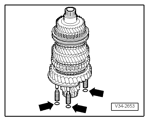
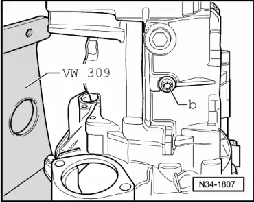
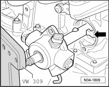
Attach bevel box to gearbox as follows:
–  Push bevel box completely onto gearbox, ensuring that splines of bevel box input shaft and differential are centred when brought together.
–  Align splines of right flange shaft and differential bevel gear, turning flange shaft if necessary.
–  If splines are correctly positioned and shafts are centred, then bevel box will slide to stop against gearbox.
  Note
Do not use securing bolts to pull bevel box onto gearbox, or bevel box will cant and bolt holes can break off.
  N34-10712
–  Tighten the 4 connecting bolts -arrows- for bevel box to gearbox (only 3 are visible in figure) → Chapter.
–  Tighten right flange shaft countersunk bolt with socket -T10107 A- → Chapter.
  A34-10040

Installing 5th/6th gears > < Removing