volkswagen Workshop Repair Guides

Volkswagen Workshop Service and Repair Manuals

Removing and installing toothed belt (vehicles with engine support bolted further away from engine) > < Removing, installing and tensioning toothed belts
Removing and installing toothed belt (vehicles with engine support bolted close to engine)
   
Removing and installing toothed belt (vehicles with engine support bolted close to engine)
Special tools and workshop equipment required
t  Locking pin -3359-
t  Pin wrench -T10020- or hexagon wrench
t  Locking pin -T10115-
t  Crankshaft stop -T10050-
t  Torque wrench -V.A.G 1331-
t  Torque wrench -V.A.G 1332-

   
t  Support bracket -10-222A- with adapters -10-222A/1-
t  Counterhold tool -T10172- with pins -T10172/4-
t  Crankshaft stop -T10100- (on vehicles with oval crankshaft belt pulley)

  Note
   
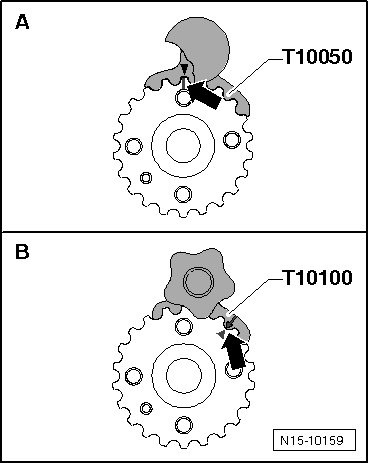
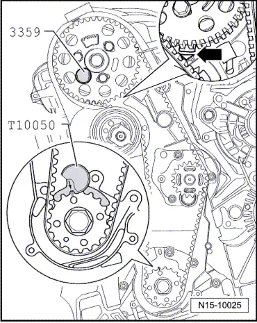
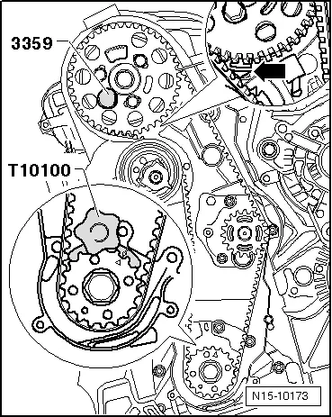
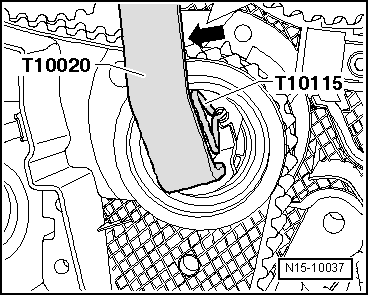
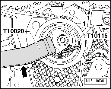
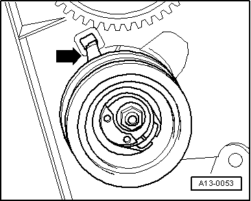
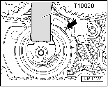
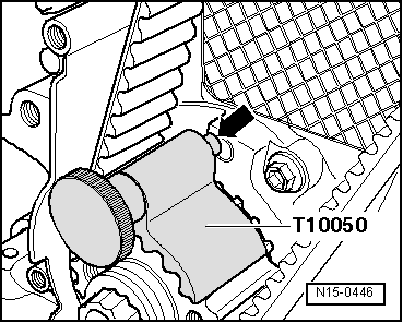
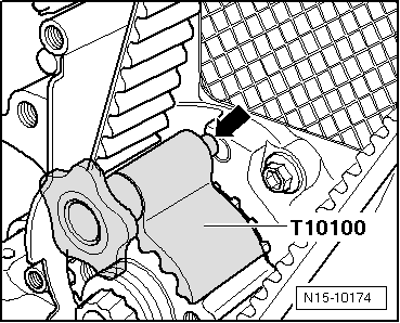
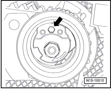
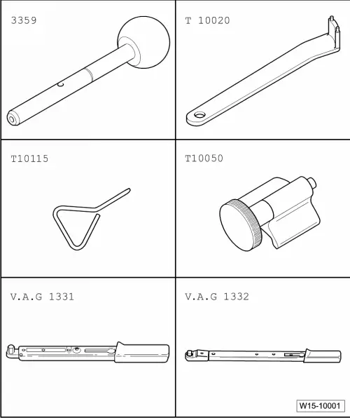
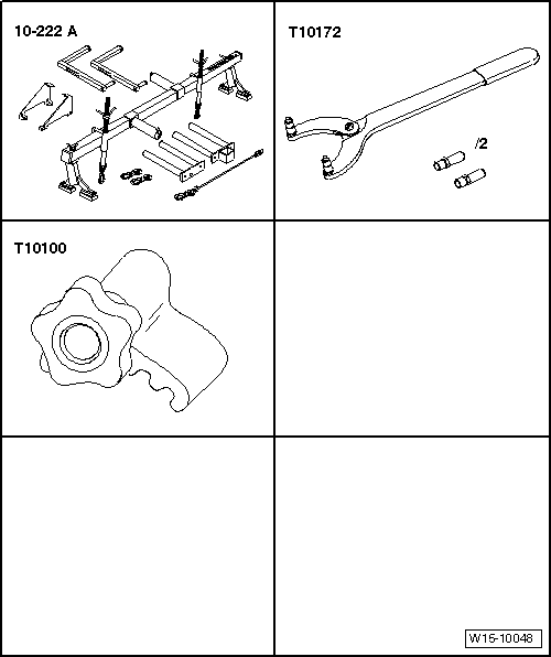
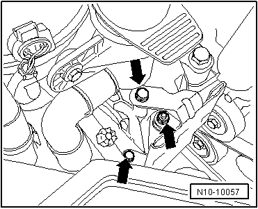
From model year 2004, a new toothed belt tensioner is installed. The tensioner has an additional hexagon hole -arrow-. To tension and release toothed belt, use Allen key instead of pin wrench -T10020-. This does not alter the procedure.
Removing
  Note
Adjustment work on toothed belts must be performed only on cold engines, as the indicator position on the tensioning element varies depending on the engine temperature.
–  Remove engine cover. → Fig.
–  Remove coolant expansion tank, coolant hoses remain connected.
–  Remove poly V-belt → Chapter.
–  Remove tensioning element for poly V-belt.
–  Remove front right wheel housing liner.
–  Remove charge air pipe between charge air cooler and turbocharger. → Chapter
–  Carefully cover or seal open ends.
–  Remove belt pulley with vibration damper.
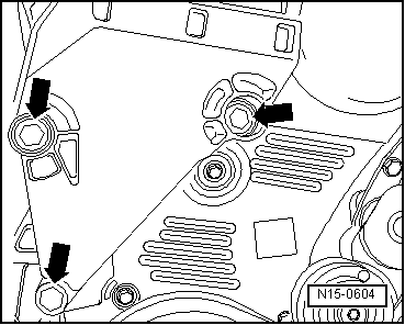
–  Remove lower and centre parts of toothed belt guard.
Golf, Golf Plus, Touran
  N15-10010
–  Set up support bracket -10-222A- with adapters -10-222A/22- and support engine in installation position.
  Note
If toothed belt is to be removed in order to remove cylinder head, set up support bracket -10-222A- with higher adapters -10-222A/13-. This will provide the space necessary for removing the cylinder head.
Passat:
  N15-0687
–  Set up support bracket -10-222A- with adapters -10-222A/1- and support engine in installation position.
Passat: If the toothed belt has to be taken off for removal of the cylinder head.
  Note
  N15-10184
Both lifting eyes for the support are located on the cylinder head, so an additional spindle -A- with bracket to support the engine must be secured on the cylinder block.
–  Set up support bracket -10-222A- with adapters -10-222A/1- and support engine in installation position with spindles -B- and -C-.
  Note
t  Spindle -A- hangs loose.
t  Unscrew filler neck for window wash system.
t  Unbolt coolant expansion tank and lay to side (hoses remain connected).
–  Pull fuel filter out of bracket.
–  Unscrew filler neck for window wash system.
  N15-10183
–  Unbolt fuel filter bracket from engine mounting -arrows-.
–  Unbolt coolant expansion tank and lay to side (hoses remain connected).
Continuation for all vehicles
  N10-10057
–  Remove securing bolts between assembly mounting and engine bracket and between assembly mounting and body -arrows- and remove complete assembly mountings.
  Note
t  The assembly mounting may only be removed if the engine is supported with support bracket -10-222A-!
t  The engine bracket must be loosened only when the assembly mounting has been removed.
  WARNING
When raising and lowering engine using support bracket -10-222A-, ensure that no components or hoses are damaged, strained or torn off.
  N13-0221
–  Raise engine with support bracket -10-222A- until both upper bolts of engine bracket can be loosened.
–  Lower engine with support bracket -10-222A- until both lower bolts of engine bracket can be loosened.
–  Remove refrigerant line securing clamp from longitudinal member.
–  Remove engine support.
–  Turn crankshaft to TDC No. 1 cylinder.
  Note
Gradual introduction of oval crankshaft toothed belt pulleys. When installing this toothed belt pulley, the crankshaft stop -T10100- must be installed to determine the TDC position instead of crankshaft stop -T10050-. Observe identification characteristics -arrows-.
  N15-0604
Characteristics of crankshaft toothed belt pulley
A = round belt pulley, lock using crankshaft stop -T10050-, TDC marking at 12 o'clock
B = oval belt pulley, lock using crankshaft stop -T10100-. TDC marking at 1 o'clock
Vehicles with round crankshaft pulley
–  Turn crankshaft to TDC No. 1 cylinder.
  Note
  N15-10159
Turn crankshaft until marking on crankshaft pulley and tooth segment of camshaft pulley is on top. The marking on the rear toothed belt guard must align with the marking on the camshaft sender wheel -arrow-.
–  Lock hub using locking pin -3359-. To do this, slide locking pin through the free elongated hole on left into hole in cylinder head.
–  Lock crankshaft toothed belt pulley with crankshaft stop -T10050 -. To do this, push crankshaft stop into teeth of belt pulley from face side.
  Note
The marks on the crankshaft toothed belt pulley and the crankshaft stop must align. When doing this, the pin of the crankshaft stop must engage in the drilling of sealing flange.
Vehicles with oval crankshaft pulley
–  Turn crankshaft to TDC No. 1 cylinder.
  Note
  N15-10025
Turn crankshaft until marking on crankshaft pulley and tooth segment of camshaft pulley is on top. The marking on the rear toothed belt guard must align with the marking on the camshaft sender wheel -arrow-.
–  Lock hub using locking pin -3359-. To do this, slide locking pin through the free elongated hole on left into hole in cylinder head.
–  Lock crankshaft toothed belt pulley with crankshaft stop -T10100-. To do this, push crankshaft stop into teeth of belt pulley from face side.
  Note
The marks on the crankshaft toothed belt pulley and the crankshaft stop must align. When doing this, the pin of the crankshaft stop must engage in the drilling of sealing flange.
Continuation for all vehicles
–  Mark direction of rotation of toothed belt.
  N15-10173
–  Loosen securing bolts -1- of camshaft pulley until the camshaft pulley can be moved within the elongated holes.
–  Loosen tensioning roller securing nut.
  N15-0232
–  Turn pin wrench -T10020- anti-clockwise until toothed belt tensioning roller can be locked with locking pin -T10115-.
  Note
A hexagon key can be used to tension or relieve tension on the tensioner.
  N15-10037
–  Now turn pin wrench -T10020- clockwise to stop and tighten securing nut -1- hand tight.
–  Remove toothed belt first from coolant pump and then from remaining pulleys.
Installing
l  Camshaft locked with locking pin -3359-.
l  The crankshaft is locked with crankshaft stop -T10050- or crankshaft stop -T10100-.
l  Tensioning roller locked with locking pin -T10115- and secured to right stop.
  Note
Adjustment work on toothed belts must be performed only on cold engines, as the indicator position on the tensioning element varies depending on the engine temperature.
  N15-10036
–  Turn camshaft pulley in its elongated holes to centre position -arrows-.
–  Fit toothed belt onto crankshaft toothed belt pulley, tensioning roller, camshaft toothed belt pulley and idler roller.
–  Then fit toothed belt on coolant pump toothed belt pulley.
  Note
  A13-0358
Ensure that tensioning roller seats correctly in rear toothed belt guard -arrow-.
–  Loosen tensioning roller securing nut and pull out locking pin -T10115-.
  A13-0053
–  Now carefully turn tensioning roller clockwise using pin wrench -T10020- until indicator is in middle of gap in the base plate -arrow-.
Ensure that securing nut does not turn as well.
–  Hold tensioning roller in this position and tighten tensioning roller securing nut as follows: 20 Nm and 45° (1/8 turn) further.
  N15-10038
–  Fit counterhold -T10172- with pins -T10172/4- as shown. Press counterhold -T10172- in direction of arrow, keeping camshaft toothed belt pulley under tension.
–  In this position, tighten camshaft toothed belt pulley securing bolts -1- to 25 Nm.
–  Remove locking pin -3359- and crankshaft stop -T10050-.
–  Turn crankshaft two rotations in engine direction of rotation until crankshaft is just before TDC No. 1 cylinder.
Vehicles with round crankshaft pulley
  N15-10028
–  Lock hub with locking pin -3359- whilst turning engine in direction of rotation.
–  Check whether crankshaft can be locked with crankshaft stop -T10050-.
If crankshaft cannot be locked:
  N15-10025
–  Loosen securing bolts -1- for camshaft toothed belt pulley.
  N15-0275
–  Turn crankshaft slightly against engine direction of rotation until the pin of the crankshaft stop is positioned just before the hole in the sealing flange -arrow-.
–  Now turn crankshaft in engine direction of rotation until crankshaft stop pin engages in sealing flange whilst turning.
Vehicles with oval crankshaft pulley
  N15-0446
–  Lock hub with locking pin -3359- whilst turning engine in direction of rotation.
–  Check whether crankshaft can be locked with crankshaft stop -T10100-.
If crankshaft cannot be locked:
  N15-10173
–  Loosen securing bolts -1- for camshaft toothed belt pulley.
  N15-0275
–  Turn crankshaft slightly against engine direction of rotation until the pin of the crankshaft stop is positioned just before the hole in the sealing flange -arrow-.
–  Now turn crankshaft in engine direction of rotation until crankshaft stop pin engages in sealing flange whilst turning.
Continuation for all vehicles
  N15-10174
–  Fit counterhold -T10172- with pins -T10172/4- as shown. Press counterhold -T10172- in direction of arrow, keeping camshaft toothed belt pulley under tension.
–  In this position, tighten camshaft toothed belt pulley securing bolts -1- to 25 Nm.
–  Remove locking pin -3359- and crankshaft stop -T10050-.
–  Turn crankshaft two rotations in engine direction of rotation until crankshaft is just before TDC No. 1 cylinder.
–  Repeat check.
  N15-10028
–  Set engine bracket against cylinder block and tighten securing bolts -A- to 40 Nm + (180°) turn further.
  Note
Before installing assembly mounting, tighten all engine bracket bolts to specified torque.
–  Install assembly mounting between engine and body (renew securing bolts).
Tightening torque of M 8 bolts: 20 Nm + (90°) turn further
Tightening torque of M 10 bolts: 40 Nm + (90°) turn further
–  Bolt engine assembly mounting to engine bracket by bringing contact surfaces together using support bracket -10-222A-.
Specified torque: 60 Nm + turn (90°) further
–  Install centre and lower parts of toothed belt guard.
–  Install belt pulley vibration damper (renew securing bolts).
Tightening torque: 10 Nm + (90°) turn further
–  Install poly V-belt → Chapter.
–  Install upper toothed belt guard.
–  Install front right wheel housing liner.
–  Install coolant expansion tank.
  N15-0604
–  Bolt fuel filter bracket to engine mounting to 8 Nm torque -arrows-.
–  Engage fuel filter in bracket.
–  Bolt on filler neck for window wash system.
–  Fit engine cover.
  N10-10057

Removing and installing toothed belt (vehicles with engine support bolted further away from engine) > < Removing, installing and tensioning toothed belts