volkswagen Workshop Repair Guides

Volkswagen Workshop Service and Repair Manuals

Assembly overview - unit injector > < Rules for cleanliness
Removing and installing pre-wired wiring harness for unit injectors and glow plugs
Special tools and workshop equipment required
   
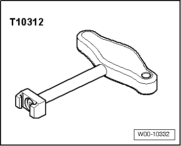
t  Puller -T10312-
  W00-10332
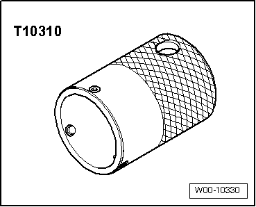
t  Special wrench -T10310-
Removing
  Caution
Removal and installation of the pre-wired wiring harness may only be undertaken by unscrewing the clips. Releasing the cable channel at the clips bends the clips which may break the cables due the excessive play. This also applies when changing the unit injectors and all work which does not require the central connector to be completely removed.
  Note
Disconnecting connectors on piezo unit injectors may only be undertaken using special tool puller -T10312-.
  W00-10330
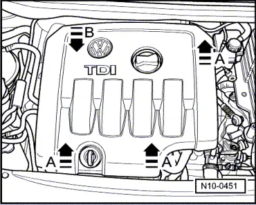
–  Remove engine cover.
To do this, pull engine cover upwards abruptly at front and right -arrows A- and then pull forwards out of rear fastening -arrow B-.
–  Remove cylinder head cover → Chapter.
–  Disconnect central connector on cylinder head.
  N10-0451
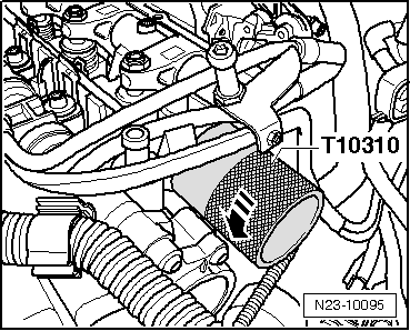
–  Fit special wrench -T10310- on adapter ring and release it by turning key through 90° (1/4 turn) in -direction of arrow-.
  N23-10095
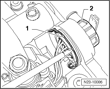
–  Pull the securing clip -1- upwards lightly with a screwdriver and press the central connector -2- through inwards.
  N23-10086
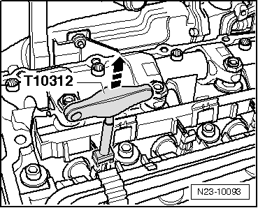
–  Slide the puller -T10312- onto the unit injector connector from the side and pull it off in -direction of arrow-. Use pointed pliers for the older connector version.
  N23-10093
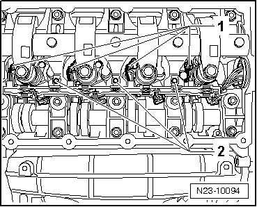
–  Pull connectors off glow plugs -1- Unscrew securing bolts -2- of steel clips and remove complete pre-wired wiring harness.
Installing
Installation is carried out in the reverse order. When installing, note the following:
–  Route pre-wired wiring harness and tighten securing bolts to 10 Nm.
  N23-10094
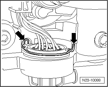
–  Guide central connector through opening in retaining frame, ensure securing clips -arrows- are seated correctly when doing this.
  N23-10088
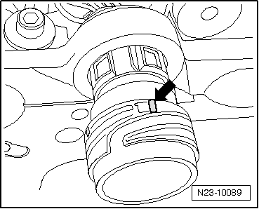
–  Fit adapter ring (colour marked „longer“ stud -arrow- faces 12 o'clock)
  N23-10089
–  Fit special wrench -T10310- on adapter ring and lock it by turning key through 90° (1/4 turn) in opposite -direction of arrow-.
  Note
When adapter ring is installed correctly the colour marked „shorter“ stud faces 12 o'clock.
–  Fit central connector to cylinder head and lock in position.
–  Install cylinder head cover → Chapter.
–  Fit engine cover.
  N23-10095

Assembly overview - unit injector > < Rules for cleanliness