| –
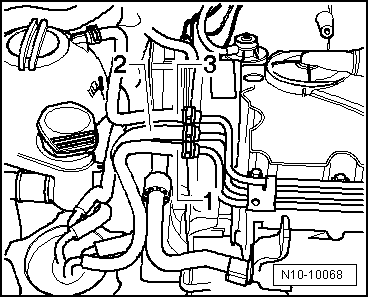
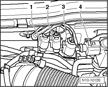
| Pull off fuel supply hose -2-, fuel return hose -1- and coolant hose -3-. |

WARNING | t
| The fuel and the fuel lines in the fuel system can become very hot (danger of scalding)! |
| t
| The fuel system is also under pressure! Before opening the system, place cloths around the connections. Then carefully loosen connection to release the pressure! |
| t
| Wear eye and hand protection when performing any type of repair work on the fuel system! |
|
| Vehicles with air conditioner |

Note | To prevent damage to condenser and also to refrigerant lines/hoses, ensure that the lines and hoses are not stretched, kinked or bent. |
| To facilitate removing and installing engine without opening refrigerant circuit: |
| –
| Secure air conditioner compressor to lock carrier so that refrigerant lines are relieved. |
| Continuation for all vehicles |
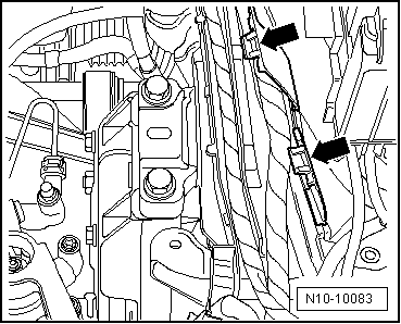
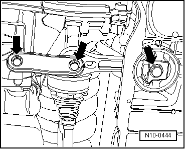
| –
| Release connector on engine control unit and pull off connector. |
| –
| Remove leadthrough for engine control unit wiring harness. |
|
|
|


 Caution