volkswagen Workshop Repair Guides

Volkswagen Workshop Service and Repair Manuals

Checking compression > < Installing
Removing and installing cylinder head
   
Removing and installing cylinder head
Special tools and workshop equipment required
t  Support bracket -10 - 222 A-
t  Adapter -10 - 222 A /8- (for Golf, Golf Plus, Passat, Eos)
t  Adapter -10 - 222 A /26- (for Touran)
t  Bracket -T10358-
t  Torque wrench (40…200 Nm) -V.A.G 1332-
t  Torque wrench (5…50 Nm) -V.A.G 1331-

Removing
   
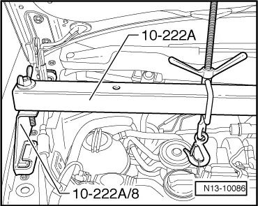
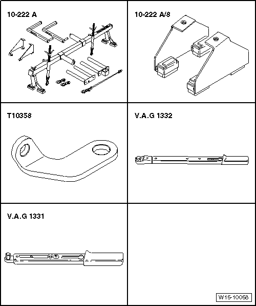
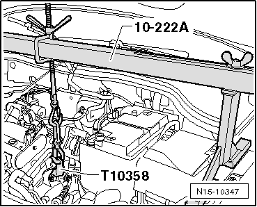
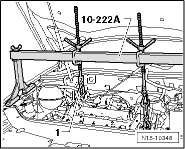
–  Install support device -10 - 222 A- with adapter -10 - 222 A /8- as shown and hook into lifting eye.
Remove following components:
t  Remove valve timing housing → Chapter
t  Remove exhaust gas recirculation valve -N18- → Chapter
t  Remove thermostat housing from cylinder head.
t  Remove fuel lines (engine codes BAG, BKG) → Chapter
t  Remove fuel lines (engine codes BLF, BLN, BLP) → Chapter
t  Remove timing chain and chain drive for oil pump (engine codes BAG, BLP, BLF) → Chapter
t  Remove timing chain and chain drive for oil pump (engine codes BKG, BLN) → Chapter
t  Removing intake manifold → Chapter.
t  Exhaust manifold
  N13-10086
–  Unscrew securing bolt for gearbox and attach bracket -T10358- as shown.
–  Attach hooks of support bracket -10 - 222 A- to bracket -T10358- as shown.
–  Turn spindle until the hooks are lightly tensioned.
  N15-10347
–  Unhook hook -1- from left lifting eye and push spindle onto left side of support bracket -10 - 222 A-.
–  Remove camshaft housing → Chapter.
–  Remove roller rocker fingers together with support elements and lay aside on a clean surface.
–  Ensure that roller rocker fingers and support elements are not interchanged.
  N15-10348
–  Loosen cylinder head bolts in sequence given and then remove completely.
–  Carefully remove cylinder head.
Installing
Prerequisite
l  The pistons must not be positioned at TDC.
  Note
t  Do not remove new cylinder head gasket from its packing until immediately before installing.
t  Handle new gasket with extreme care. Damage will cause leakage.
–  Place clean cloths in cylinders so that no dirt or emery cloth particles can get in between cylinder wall and piston.
–  Now carefully clean sealing surfaces of cylinder head and cylinder block. When doing this, ensure that surfaces are not scored or scratched (if abrasive paper is used, grade must not be less than 100).
–  Carefully remove metal particles, emery residue and cloths.
–  Set No. 1 cylinder piston to top dead centre and then turn crankshaft back slightly.
–  Fit new cylinder head gasket. Inscription (Part No.) must be readable.
–  Fit cylinder head. When doing this, observe centring pins in cylinder block.
–  Insert new cylinder head bolts and tighten hand-tight.
  N15-0026
–  Tighten cylinder head bolts in tightening sequence as follows:
–  Tighten all bolts to 30 Nm.
–  Then turn all bolts 90° further using a rigid wrench.
–  Then turn all bolts 90° further again.
–  Install supporting elements in cylinder head and fit respective roller rocker finger onto respective valve stem end or supporting element.
–  Install camshaft housing → Chapter.
–  Install timing chain and chain drive for oil pump (engine codes BAG, BLP, BLF) → Chapter.
–  Install timing chain and chain drive for oil pump (engine codes BKG, BLN) → Chapter.
–  Adjust valve timing → Chapter.
–  Install control housing → Chapter.
–  Install exhaust gas recirculation valve -N18- → Chapter
Further assembly is basically the reverse of the dismantling sequence.
  V15-0738

Checking compression > < Installing