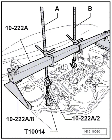
volkswagen Workshop Repair Guides

Volkswagen Workshop Service and Repair Manuals

Installing > < Removing and installing cylinder head
Removing
Removing
  Caution
When doing any repair work, especially in the engine compartment, pay attention to the following due to the cramped conditions:
t  Route all the various lines (e.g. for fuel, hydraulics, activated charcoal filter system, coolant, refrigerant, brake fluid and vacuum) and electrical wiring in their original positions.
t  To avoid damage to lines, ensure sufficient clearance to all moving or hot components.
–  First check whether a coded radio is fitted. If so, obtain anti-theft coding.
–  With the ignition switched off, disconnect battery earth strap.
–  First remove main drive toothed belt → Chapter.
–  Remove camshaft housing → Chapter.
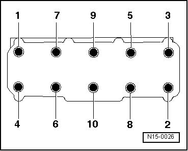
–  Remove roller rocker fingers together with support elements and lay aside on a clean surface.
–  Ensure that roller rocker fingers and support elements are not interchanged.
  WARNING
Steam may escape when expansion tank is opened. Wear eye protection and protective clothing to avoid eye injuries and scalding. Cover cap with cloth and open carefully.
–  Open and close expansion tank cap to release pressure in cooling system.
–  Drain coolant → Chapter.
–  Loosen hose clips and pull coolant hoses off coolant thermostat housing.
–  Remove oil dipstick guide tube.
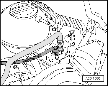
  WARNING
Fuel supply lines are under pressure! Wear eye protection and gloves to avoid injuries and skin contact. Before loosening hose connections, wrap a cloth around the connection. Then release pressure by carefully pulling hose off connection.
   
–  Remove fuel supply line -2-. To do this, press release buttons.
–  Seal lines so that fuel system is not contaminated by dirt.
–  Observe rules for cleanliness → Chapter.
–  Loosen or separate the following components:
t  Hose from activated charcoal filter to intake manifold.
t  Vacuum hose from brake servo to intake manifold.
t  Connector of knock sensor 1 -G61- (on rear of cylinder block), the connector of intake manifold pressure sender -G71- and intake air temperature sender -G42-.
t  Connector of engine speed sender -G28-.
t  Connector of coolant temperature sender -G62-, oil pressure switch -F1- and exhaust gas recirculation valve -N18-.
t  Connector of throttle valve control module -J338-.
t  Connector of injectors.
t  Connector from heated vacuum valve on oil separator.
t  Hose from crankcase breather on intake manifold.
–  Pull off or disconnect all other electrical connections as necessary from engine and lay to side.
–  Detach front exhaust pipe from exhaust manifold → Chapter.
–  Remove securing bolt for toothed belt rear guard (near right-hand lifting eye).
  Note
Both lifting eyes are located on the cylinder head, so an additional bracket must be secured to the cylinder block to support the engine.
–  Remove bracket for idler roller → Item.
–  Attach bracket -T10014- -as illustrated- to cylinder block using threaded hole for idler roller. Specified torque: 20 Nm
  A20-1065
–  Lift engine slightly using second spindle -A- until spindle -B- is relieved.
–  Remove spindle -B-.
–  Pull clamp securing coolant pipe to coolant pump off thermostat housing.
  N15-10080
–  Loosen cylinder head bolts in sequence given and then remove completely.
–  Carefully remove cylinder head.
  N15-0026

Installing > < Removing and installing cylinder head