volkswagen Workshop Repair Guides

Volkswagen Workshop Service and Repair Manuals

Engine lubrication > < Removing and installing inlet camshaft control valve 1N205
Removing and installing camshafts
Special tools and workshop equipment required
   
t  Two-arm puller -T40001-
  W00-10104
t  Counterhold tool -3036-
t  Sealant -D 154 103 A1-
Removing camshafts
  Note
t  The sealing surfaces on bottom of retaining frame and top of cylinder head must not be reworked.
t  The camshaft bearings are integrated into the cylinder head and the retaining frame. The toothed belt must be relieved of tension before the retaining frame is removed.
t  Renew camshaft oil seal and sealing cap if retaining frame has been unfastened.
–  Remove camshaft adjuster → Chapter.
–  Remove toothed belt:
   Vehicles with split toothed belt guard → Chapter.
   Vehicles without split toothed belt guard → Chapter.
  W00-0270
–  Loosen securing bolt for camshaft pulley and unscrew approx. 10 mm (use counterhold -3036-).
  A13-0381
–  Pull camshaft sprocket off with two arm puller -T40001-, claw -T40001/6- and claw -T40001/7-. Two arm puller -T40001- is supported on securing bolt -arrow-.
–  Remove securing bolt and camshaft pulley.
–  Remove rear toothed belt guard from cylinder head.
–  Loosen retaining frame bolts evenly working from outside inwards and remove retaining frame.
–  Carefully lift out the camshafts and place them down on a clean surface.
  N15-10476
–  Remove old sealant from groove in retaining frame as well as from sealing surfaces.
–  Prevent dirt and residual sealant from entering cylinder head.
Installing camshafts
  Note
t  Sealing surfaces must be free of oil and grease.
t  The pistons must not be positioned at TDC.
t  Ensure that all roller rocker fingers are properly seated on valve stem ends.
–  Oil running surfaces of camshafts.
  N15-10105
–  Insert camshafts carefully in the camshaft bearings of cylinder head. Cams -A- of cylinder 4 must face each other.
  N15-10109
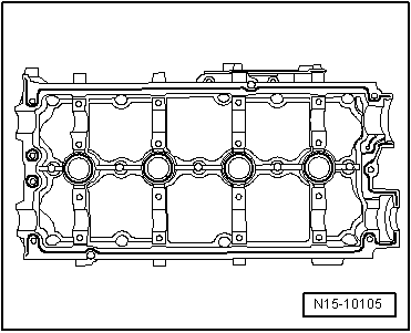
–  Apply even, slightly projecting sealant bead (D 154 103 A1) into clean groove of retaining frame.
  Note
t  Sealant must not be applied too thickly. If necessary wipe away excess sealant with a lint-free cloth.
t  The retaining frame must be positioned and bolted on without interruption because the sealant begins to harden immediately when the sealing surfaces come into contact with each other.
t  Observe expiry date of sealing compound.
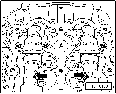
–  Place retaining frame on cylinder head.
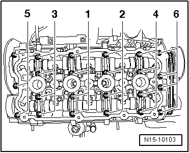
–  Tighten bolts lightly in several stages, working from inside outwards.
  N15-10105
–  Then tighten bolts in the sequence shown to 8 Nm + 1/4 (90°) turn further.
–  Drive in sealing cap → Item about 1…2 mm using thrust piece -3334-.
–  Install camshaft oil seal → Chapter.
–  Install rear toothed belt guard.
–  Insert parallel key into camshaft.
  N15-10103
–  Install camshaft toothed belt pulley. To tighten bolt, hold camshaft toothed belt pulley in position using counterhold -3036-. Specified torques → Chapter
  Note
t  When turning the camshaft, the pistons must not be at TDC. This could otherwise result in damage to valves and pistons.
t  Ensure the parallel key is correctly seated.
–  Install toothed belt.
   Vehicles with split toothed belt guard → Chapter.
   Vehicles without split toothed belt guard → Chapter.
–  Install camshaft adjuster → Chapter.
–  Install cylinder head cover → Chapter.
Further assembly is basically the reverse of the dismantling sequence.
  A13-0381

Engine lubrication > < Removing and installing inlet camshaft control valve 1N205