volkswagen Workshop Repair Guides

Volkswagen Workshop Service and Repair Manuals

Valve stem seals > < Installing
Removing and installing camshaft control valves
   
Removing and installing camshaft control valves
Special tools and workshop equipment required
t  Torque wrench -V.A.G 1783-
t  Torx bit set -V.A.G 1766-
t  1/4" drive ratchet -VAS 6234-
t  Special wrench, long reach -T10072-

Removing:
–  Remove intake manifold → Chapter.
   
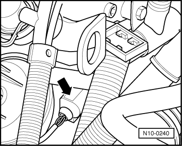
–  Pull off 2-pin connector from coolant temperature sender -G62--arrow-.
–  Drain coolant → Chapter.
–  Remove thermostat housing → Chapter.
–  Remove cylinder head cover → Chapter.
  Note
Before removing connectors, mark each connector and component to which it belongs.
  N10-0240
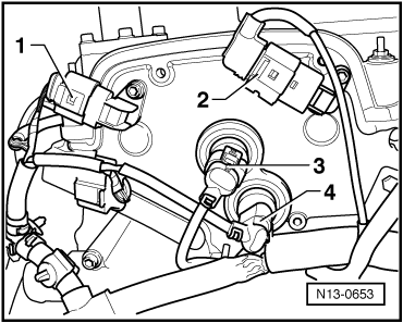
–  Pull connectors off Hall sender -G40--1- and Hall sender 2 -G163--2-.
–  Pull off connectors -3- and -4-.
–  Move wiring harness clear.
  N13-0653
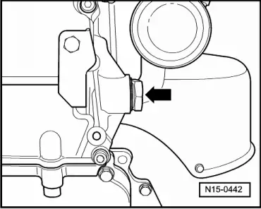
–  Remove chain tensioner for camshaft timing chain -arrow-.
  N15-0442
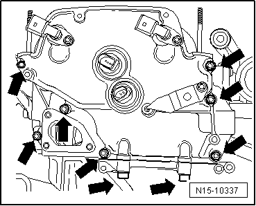
–  Unscrew securing bolts -arrows- for cover.
–  Cover can be prised off carefully when all securing bolts have been removed.
  Caution
t  In order to make sure that valves do not become jammed when they are being removed, do not completely unscrew securing bolts of camshaft control valves.
t  Cover lower chain housing carefully so that no parts can fall into it.
  N15-10337
–  Unscrew securing bolts for camshaft control valves approx. 3 mm (5 turns) with socket -T10072--arrows-.
–  Pull camshaft control valve out of seat in control housing and slide it along loosened bolts.
–  Completely remove securing bolts and pull camshaft control valve out of control housing.
Installing:
  Caution
t  The valve seat in the control housing must not be scored or scratched.
t  The camshaft control valves and the control housing must be free of dirt and soiling.
t  Ensure the camshaft control valves are protected from knocks and impacts.
t  Only unpack the new camshaft control valves immediately prior to installation.
t  The camshaft control valves must not be pulled into their seat with the securing bolts. Only insertion by hand is permitted.
–  Moisten seals with clean engine oil.
–  Carefully insert camshaft control valve into housing and push vertically to valve axis to stop by hand.
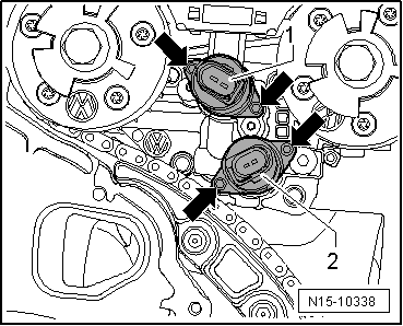
  N15-10338
–  Tighten securing bolts -arrows- to 3.8 Nm.
-1-Camshaft control valve 1 -N205-.
-2-Exhaust camshaft control valve 1 -N318-.
–  Clean sealing surface a on cover and cylinder head.
  N15-10338
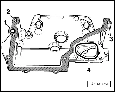
–  Lubricate O-ring for oil channel seal -1- and insert in cover.
–  Check that dowel sleeves -2- and -3- are inserted.
–  Insert O-ring -4- in cover.
  A13-0779
–  Remove old sealant from 3 mm holes in cylinder head gasket -arrows-.
–  Fill 3 mm holes in cylinder head gasket with sealant -D 176 501 A1-. Coat sealing surface of cover with sealant -D 176 501 A1- and immediately install.
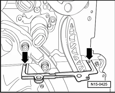
  N15-0425
–  First insert all securing bolts -arrows- and tighten lightly.
–  Then tighten M8 securing bolts → Item to 23 Nm and M6 securing bolts → Item to 8 Nm.
–  Install chain tensioner for camshaft timing chain → Item and tighten to 40 Nm.
–  Install cylinder head cover → Chapter and intake manifold → Chapter.
Further assembly is basically the reverse of the dismantling sequence.
  N15-10337

Valve stem seals > < Installing