volkswagen Workshop Repair Guides

Volkswagen Workshop Service and Repair Manuals

Removing and installing camshaft control valves > < Removing
Installing
Installing
   
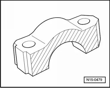
Lightly coat contact surfaces of bearing caps 7 and 8 with solid lubricating paste -G 052 723 A2- before installing.
Prerequisites
l  When camshafts are installed, cams for No. 1 cylinder must point upwards.
–  Install supporting elements in cylinder head and fit respective roller rocker finger onto respective valve stem end or supporting element.
  N15-0479
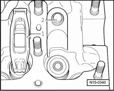
–  Ensure that all roller rocker fingers -1- seat properly on valve stem ends and are clipped into their respective support elements -2-.
–  Oil cams and running surfaces of camshafts.
–  Carefully place each camshaft in its respective bearing in the cylinder head. When doing this, observe camshaft identification → Fig..
  Note
  N15-0340
t  Observe fitting position of bearing caps:
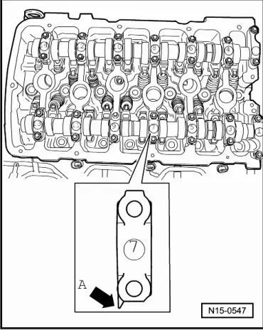
t  Points of bearing caps -arrow A- of inlet and outlet camshafts face outwards.
t  Identification on bearing caps is right side up when viewed from inlet side.
  N15-0547
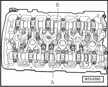
A - inlet camshaft
–  Tighten bearing caps 5 and 9 alternately and diagonally to 5 Nm + 1/8 turn (45°).
–  Install bearing caps 1 and 13 and tighten to 5 Nm + 1/8 turn (45°).
–  Install bearing cap 7 and tighten to 5 Nm and turn 1/8 (45°) further.
–  Install bearing caps 3 and 11 and also tighten to 5 Nm + 1/8 turn (45°).
  N15-0350
B - exhaust camshaft
–  Tighten bearing caps 6 and 10 alternately and diagonally to 5 Nm + 1/8 turn (45°).
–  Install bearing caps 2 and 14 and tighten to 5 Nm + 1/8 turn (45°).
–  Install bearing cap 8 and tighten to 5 Nm and turn 1/8 (45°) further.
–  Install bearing caps 4 and 12 and also tighten to 5 Nm + 1/8 turn (45°).
  N15-0350
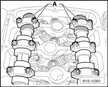
–  Position camshafts in cylinder head to TDC No. 1 cylinder. Cams -A- of cylinder 1 must face each other.
  N15-10391
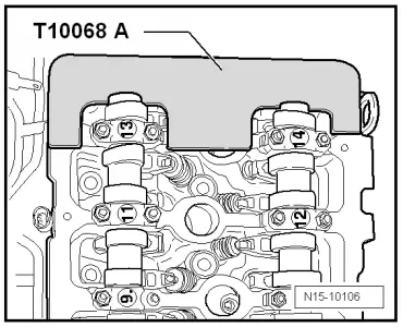
–  The camshaft bar -T10068 A- must engage in grooves in both shafts.
–  Before installing, check valve timing housing strainer for soiling → Fig..
–  Before installing valve timing housing, lubricate valve timing housing surfaces contacting camshaft seals.
–  Lubricate seals on camshafts and slowly push valve timing housing over camshaft seals.
  N15-10106
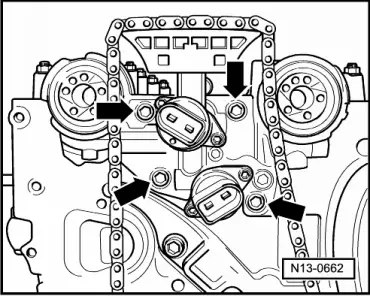
–  Install control housing and insert securing bolts -arrows- with locking fluid -D 000 600 A2-. Specified torque 8 Nm.
–  Install camshaft adjuster with camshaft timing chain → Chapter.
–  Clean sealing surface on cover and cylinder head.
  N13-0662
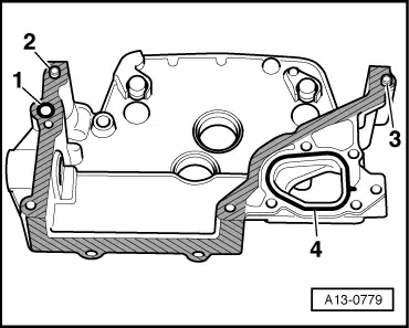
–  Lubricate O-ring for oil channel seal -1- and insert in cover.
–  Check that dowel sleeves -2- and -3- are inserted.
–  Insert O-ring -4- in cover.
  A13-0779
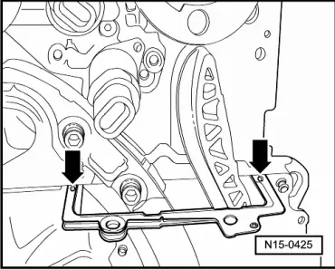
–  Remove old sealant from 3 mm holes in cylinder head gasket -arrows-.
–  Fill 3 mm holes in cylinder head gasket with sealant -D 176 501 A1-. Coat sealing surface of cover with sealant -D 176 501 A1- and immediately install.
  N15-0425
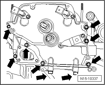
–  First insert all securing bolts -arrows- and tighten lightly.
–  Then tighten M8 securing bolts → Item to 23 Nm and M6 securing bolts → Item to 8 Nm.
–  Install chain tensioner for camshaft timing chain → Item and tighten to 40 Nm.
–  Install cylinder head cover → Chapter and intake manifold → Chapter.
  N15-10337

Removing and installing camshaft control valves > < Removing