
Golf Mk5
| Assembly overview - fuel tank |

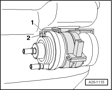
| 1 - | Supply line |
| q | Black |
| q | Check for secure seating. |
| 2 - | Return line |
| q | Blue |
| q | Check for secure seating. |
| 3 - | Seal |
| q | Renew. |
| q | When installing, fit dry in fuel tank opening. |
| q | Moisten with fuel only when installing flange. |
| 4 - | Fuel delivery unit |
| q | Removing and installing → Chapter |
| q | If fuel delivery unit was renewed, adapt engine control unit to fuel pump → Vehicle diagnostic tester„Guided functions“ |
| q | Checking fuel pump → Chapter. |
| q | Note installation position on fuel tank → Fig.. |
| q | With fuel gauge sender -G-. |
| q | Removing and installing fuel gauge sender → Chapter. |
| q | Clean strainer if soiled. |
| 5 - | Locking ring, 110 Nm |
| q | Check for secure seating. |
| q | Remove and install using wrench -T10202-. |
| 6 - | Breather line |
| q | From gravity valve to activated charcoal filter |
| q | Clip onto bracket in wheel housing |
| q | To pull off, press release button on connection. |
| 7 - | Cap |
| q | Renew if damaged |
| 8 - | Securing bolt |
| 9 - | Tank flap unit |
| q | With rubber cup. |
| q | Removing and installing → General body repairs, exterior; Rep. gr.55. |
| 10 - | Earth connection |
| q | Check for secure seating. |
| 11 - | 10 Nm |
| 12 - | Protective plate |
| q | For fuel filler neck |
| q | Ensure that earth connection is securely seated |
| 13 - | 10 Nm |
| 14 - | Cable retainer |
| q | Clipped onto protective plate |
| 15 - | Fuel gauge sender 2 -G169- |
| q | Removing and installing → Chapter |
| q | Note installation position on fuel tank → Fig.. |
| 16 - | Suction-jet pump |
| q | Clipped onto fuel gauge sender 2 -G169- |
| q | Removing and installing → Chapter |
| 17 - | Fuel tank |
| q | When removing, support using engine and gearbox jack -V.A.G 1383 A-. |
| q | Removing and installing → Chapter |
| 18 - | Securing strap |
| q | Note installation position. |
| 19 - | 25 Nm |
| q | Renew. |
| q | To secure the securing straps for the fuel tank, only bolts with loose washers must be used. If different bolts are used, the securing straps might twist during tightening. Bolts → ETKA (electronic parts catalogue). |
| 20 - | Heat shield |
| q | Riveted to exhaust pipe mounting |
| 21 - | 3 Nm |
| 22 - | Breather line |
| q | White |
| q | From activated charcoal filter to activated charcoal filter solenoid valve 1 -N80- |
| q | Do not kink. |
| q | To pull off, press release button on connection. |
| q | Clipped onto fuel tank. |
| 23 - | Vacuum line |
| q | Green |
| q | From fuel system diagnosis pump -V144- to intake manifold. |
| q | Clipped onto fuel tank. |
| q | Check for secure seating. |
| 24 - | Supply line |
| q | To fuel rail. |
| 25 - | Fuel filter |
| q | Installation position: arrow indicates direction of flow. |
| q | Removing and installing → Chapter |
| 26 - | 8 Nm |
 Note
Note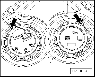
|
|