| Component | Specified torque |
| Suspension strut to wheel bearing housing | 70 Nm + 90° |
| Suspension strut to body (suspension turret) | 15 Nm + 90° |
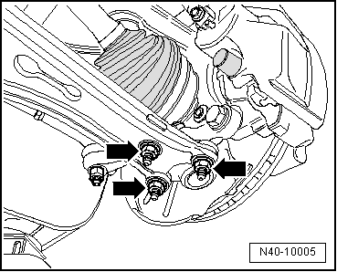
| Swivel joint to cast steel suspension link | 60 Nm |
| Swivel joint to sheet steel or forged aluminium suspension link | 100 Nm |
Coupling rod to suspension strut| t
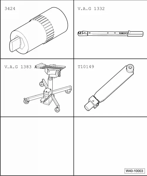
| Counterhold on multi-point socket of joint pin |
| 65 Nm |
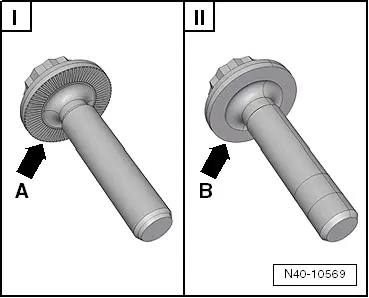
| Drive shaft to wheel hub „hexagon bolt“ | 200 Nm + 180° |
| Drive shaft to wheel hub „twelve-point head bolt with ribbing“ | 70 Nm + 90° |
| Drive shaft to wheel hub „twelve-point head bolt without ribbing“ | 200 Nm + 180° |

 Caution
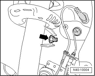
 WARNING
 Note
Note