volkswagen Workshop Repair Guides

Volkswagen Workshop Service and Repair Manuals

Removing and installing drive shafts with triple roller joint AAR3300i > < Removing and installing right drive shaft with (push-on) constant velocity slip joint
Removing and installing drive shafts with triple roller joint AAR2600i
Special tools and workshop equipment required
   
t  Torque wrench -V.A.G 1332-
  W00-0428
t  Wedge -T10161-
  Caution
When removing and installing drive shafts, do not allow them to hang free and stop against joints due to over bending.
Removing
–  Loosen drive shaft bolt at wheel hub:
t  Hexagon bolt → Chapter
t  Twelve-point head bolt with ribbing → Chapter
t  Twelve-point head bolt without ribbing → Chapter
  Caution
Wheel bearings must not be subjected to load after bolt securing drive shaft to wheel hub has been loosened.
If wheel bearings are loaded with weight of vehicle, bearing will be damaged. This reduces the service life of the wheel bearing.
It is not permissible to turn drive shaft bolt more than 90° anti-clockwise if vehicle is standing on the wheels.
Do not attempt to move the vehicle without the drive shafts fitted as this would damage the wheel bearing. If a vehicle nevertheless has to be moved, comply with the following:
t  Install an outer joint instead of the drive shaft.
t  Tighten outer joint to 120 Nm.
–  Remove wheel.
–  Remove lower noise insulation → Rep. gr.50.
  W00-10018
–  Remove nuts -arrows-.
–  Pull wheel bearing housing with swivel joint out of suspension link.
–  Pull drive shaft out of wheel hub and tie up to body.
  N40-10005
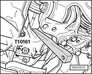
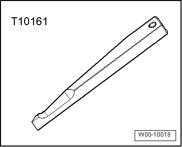
–  Insert wedge-T10161- between gearbox housing and triple roller joint.
–  Press inner joint out of gearbox by striking wedge -T10161- with a hammer.
–  Remove drive shaft.
Installing
–  Fit new retaining ring into groove of joint pin.
–  Mesh outer and inner splines of joint body and gearbox.
–  Slide drive shaft into joint body to stop by hand.
–  Now »suddenly« push joint body into gearbox.
The joint travel can be used for the »sudden push«. Do not, however, pull the drive shaft too far out of the joint body.
  Note
Never use a hammer or other striking tool!
–  Check that drive shaft is seated securely in gearbox by pulling on joint body against resistance of retaining ring.
For this check, pull only on joint body and not on drive shaft.
–  Guide outer joint into wheel hub splines as far as possible.
–  Attach lower noise insulation → Rep. gr.50.
  A40-0533
–  Bolt swivel joint to suspension link -arrows-.
  Note
Ensure that bellows are not damaged or twisted.
–  Tighten drive shaft bolt at wheel hub:
t  Hexagon bolt → Chapter
t  Twelve-point head bolt with ribbing → Chapter
t  Twelve-point head bolt without ribbing → Chapter
  Caution
During this step, vehicle must not be standing on its wheels.
The wheel bearing can be damaged by the weight of the vehicle if the bolt is loosened.
  N40-10005
Distinguishing features between twelve-point head bolt with ribbing and twelve-point head bolt without ribbing.
The twelve-point head bolt are only distinguishable on the contact surfaces -arrow A- and -arrow B-.
I - Twelve-point head bolt with ribbing -arrow A-
II - Twelve-point head bolt without ribbing -arrow B-
–  Install wheel and tighten bolts or nuts → Chapter.
  N40-10569
Specified torques
ComponentSpecified torque
Swivel joint to cast steel suspension link
t  Use new nuts
60 Nm
Swivel joint to sheet steel or forged aluminium suspension link
t  Use new nuts
100 Nm
Drive shaft to wheel hub „hexagon bolt“
t  Use new bolt
200 Nm + 180°
Drive shaft to wheel hub „twelve-point head bolt with ribbing“
t  Use new bolt
70 Nm + 90°
Drive shaft to wheel hub „twelve-point head bolt without ribbing“
t  Use new bolt
200 Nm + 180°


Removing and installing drive shafts with triple roller joint AAR3300i > < Removing and installing right drive shaft with (push-on) constant velocity slip joint