volkswagen Workshop Repair Guides

Volkswagen Workshop Service and Repair Manuals

Removing and installing drive shafts with triple roller joint AAR2600i > < Removing and installing left drive shaft with (push-on) constant velocity slip joint
Removing and installing right drive shaft with (push-on) constant velocity slip joint
   
Removing and installing right drive shaft with (push-on) constant velocity slip joint
Special tools and workshop equipment required
t  Multi-purpose tool -VW 771-
t  Tensioning strap -T10038-
t  Drive shaft puller -T10382-
t  Torque wrench -V.A.G 1332-
t  Angle wrench -V.A.G 1756-

  Caution
When removing and installing drive shafts, do not allow them to hang free and stop against joints due to over bending.
Removing
–  Loosen drive shaft bolt at wheel hub:
t  Twelve-point head bolt with ribbing → Chapter
t  Twelve-point head bolt without ribbing → Chapter
  Caution
Wheel bearings must not be subjected to load after bolt securing drive shaft to wheel hub has been loosened.
If wheel bearings are loaded with weight of vehicle, bearing will be damaged. This reduces the service life of the wheel bearing.
It is not permissible to turn drive shaft bolt more than 90° anti-clockwise if vehicle is standing on the wheels.
Do not attempt to move the vehicle without the drive shafts fitted as this would damage the wheel bearing. If a vehicle nevertheless has to be moved, comply with the following:
t  Install an outer joint instead of the drive shaft.
t  Tighten outer joint to 120 Nm.
–  Remove lower noise insulation → Rep. gr.50.
–  Remove wheel.
   
–  Remove nuts -arrows-.
–  Pull wheel bearing housing with swivel joint out of suspension link.
–  Unbolt coupling rods from anti-roll bars on both sides.
–  Push drive shaft outer joint out of wheel hub by hand.
–  Secure drive shaft to prevent it from falling.
  N40-10005
–  Set up drive shaft puller -T10382-.
For the constant velocity slip joint -1-, notch -arrow- in the puller plate -T10382/1- must face the spindles -T10382/2-.
–  Assemble drive shaft puller -T10382- complete with multi-purpose tool -VW 771-.
  Note
In order to pull the drive shaft out of the gearbox using the drive shaft puller -T10382-, the suspension strut with all attachments must be pulled to the rear.
  N40-10297
–  Using tensioning strap -T10038- e.g. on lifting platform arm, pull suspension strut with attachments back until the drive shaft puller -T10382- can be applied parallel to drive shaft.
  N40-10284
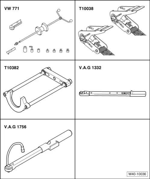
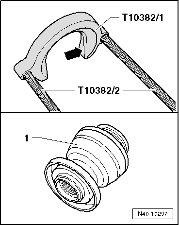
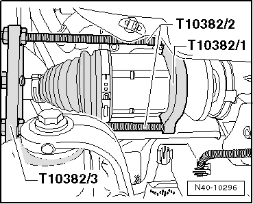
–  Set up drive shaft puller -T10382- and pull out drive shaft.
–  Remove drive shaft from vehicle.
Installing
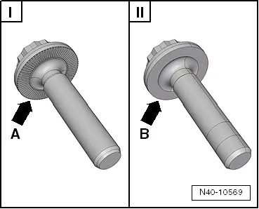
Remove any paint residue and/or corrosion on thread and splines of outer joint.
–  Insert new retaining ring in groove in stub shaft on gearbox.
–  Lightly grease splines of stub shaft with universal grease -G 060 735 A2-
–  Mesh outer and inner splines of gearbox and constant velocity slip joint.
–  Slide drive shaft into constant velocity joint to stop by hand.
–  Now push constant velocity joint onto stub shaft of gearbox with a »sudden, hard push«.
  Note
Never use a hammer or other striking tool!
–  Check that constant velocity slip joint is seated securely by pulling on constant velocity joint against resistance of retaining ring.
  Caution
For this check, pull only on constant velocity slip joint, not on drive shaft.
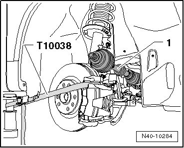
–  Detach tensioning strap -T10038-.
–  Guide outer joint into wheel hub splines as far as possible.
  N40-10296
–  Bolt swivel joint to suspension link -arrows-.
  Note
Ensure that bellows are not damaged or twisted.
–  Attach lower noise insulation → Rep. gr.50.
–  Tighten drive shaft bolt at wheel hub:
t  Twelve-point head bolt with ribbing → Chapter
t  Twelve-point head bolt without ribbing → Chapter
  Caution
During this step, vehicle must not be standing on its wheels.
The wheel bearing can be damaged by the weight of the vehicle if the bolt is loosened.
  N40-10005
Distinguishing features between twelve-point head bolt with ribbing and twelve-point head bolt without ribbing.
The twelve-point head bolt are only distinguishable on the contact surfaces -arrow A- and -arrow B-.
I - Twelve-point head bolt with ribbing -arrow A-
II - Twelve-point head bolt without ribbing -arrow B-
–  Install wheel and tighten bolts or nuts → Chapter.
  N40-10569
Specified torques
ComponentSpecified torque
Swivel joint to cast steel suspension link
t  Use new nuts
60 Nm
Swivel joint to sheet steel or forged aluminium suspension link
t  Use new nuts
100 Nm
Drive shaft to wheel hub „twelve-point head bolt with ribbing“
t  Use new bolt
70 Nm + 90°
Drive shaft to wheel hub „twelve-point head bolt without ribbing“
t  Use new bolt
200 Nm + 180°


Removing and installing drive shafts with triple roller joint AAR2600i > < Removing and installing left drive shaft with (push-on) constant velocity slip joint